


Compared to yesterday, more and more things are moving towards digital! If the FM tuner is capable of delivering 100% pure digital music then why we need to restrict ourselves still listening in Analog? Let's go digital!
In this project we will learn how to implement IR remote controlled I2S(inter-IC sound bus) output FM tuner with Radio Data System (RDS) using ESP-01.
We are all familiar with RRD-102 V.2 module and connection. We are also familiar with many Arduino libraries available to control the RRD-102 V.2 module. Most of the Arduino libraries comes with RDS information display using LCD or OLED. There are many IR remote control libraries available. There are many OLED and LCD libraries available for graphical and text display.
I am not going to discuss any of the above in details here.
There are many FM Tuner family of ICs with I2S digital output available from Silabs, Quintic, RDA Microelectronics, etc.,
For DIY enthu the deciding factors are different. Simple foot-print for easy and quick prototyping using bread board, easily available, BOM Cost and circuit complexity(few external components)
RDA Microelectronics FM tuners mainly available in MSOP10, SOIC8, SOP16 and QFN packages. Most of the SOP16 and QFN comes with I2S digital output support.
Since the internal I2C bus address and register organization remains the same, we can use any of the RDA FM tuner Arduino Library and are compatible across family including 5802, 5820 series.
All the SOP16 and QFN package ICs comes with 3 GPIO pins. These GPIOs can be set to High, Low or used to Interrupt generation. Please refer to datasheet for more details.
The basic connection and software are exactly same as conventional wiring except very few minor changes.
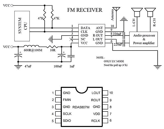
Conventional FM tuner with I2C interface:In this project we will be controlling the I2C bus by using ESP-01.
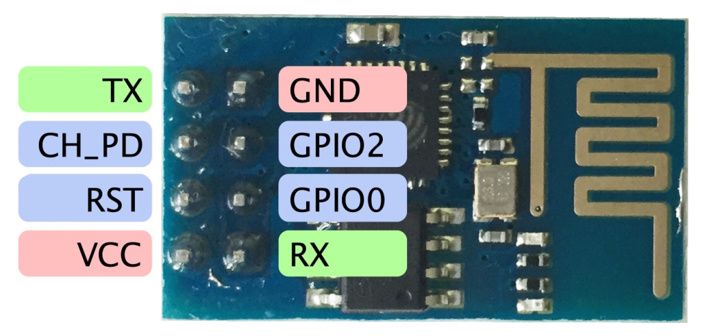
ESP-01 pin map
- GPI00 - SDA(FM tuner + OLED or LCD + EEPROM)
- GPIO2 - SCL(FM tuner + OLED or LCD + EEPROM)
- GPIO3 - Rx - IR receiver
The optional EEPROM can be added to the same I2C bus which can be used to store the previous state of the channel frequency and any other user preferred data or settings so that during next power ON the ESP-01 will load the settings from the EEPROM. We can emulate and implement the EEPROM using the FLASH MEMORY used by ESP-01. Just by adding external EEPROM we can improve the reliability of the FLASH MEMORY by avoiding frequent read/write cycle of FLASH unnecessarily.
The I2S bus has three signals:
- continuous serial clock (SCK)
- word select (WS)
- serial data (SD)
If we enable the I2S output of RDA FM tuner, then the following GPIO pins will be assigned to the I2S signals
- PIN# 01 - GPIO1 - WS
- PIN# 16 - GPIO2 - SD
- PIN# 15 - GPIO3 - SCK
Even if we enable the I2S, still the analog output availabe on LOUT & ROUT pins concurrently!
To Enable the I2S output we need to set only 3 bits to "1".
- REGister 04H bit#6 I2S_ENABLE = "1"
- REGister 06H bit#9 data_signed = "1"
- REGister 06H bits[7:4] I2S_SW_CNT[4:0] - 4'b1000 for 48kbps
The default audio sample rate is 8ksps. User should select REGister 0x06H bits to select the higher sampling rate. Please refer to the CODE section for REGister 0x04H and REGister 0x06H details.
After enabling the above 3 bits, the GPIOs will output the I2S signals. We can directly connect these three pins to any suitable I2S Audio DAC.
You can refer to any of the SOP16 or QFN package RDA FM tuner datasheet for more register and programming options.
We can connect the I2S signals to A2DP bluetooth Tx module or ESP32 for further audio processing or streaming.
- //* I2S OUTPUT FM TUNER *//
- // TUNER: RDA7088
- // CPU: ESP-01S or ESP-01
- // OLED: 128x32 or 128x64
- // IR: NEC 38kHz 21 Keys
- // OUTPUT: I2S (16bits upto 48kHz)
- // I2S DAC: PCM5102A or MAX98357A or UDA1334A or PCM5100
- // INPUT: 5V or 3.7V Li
- // VERSION: 1.0 // 30th DEC 2022 //
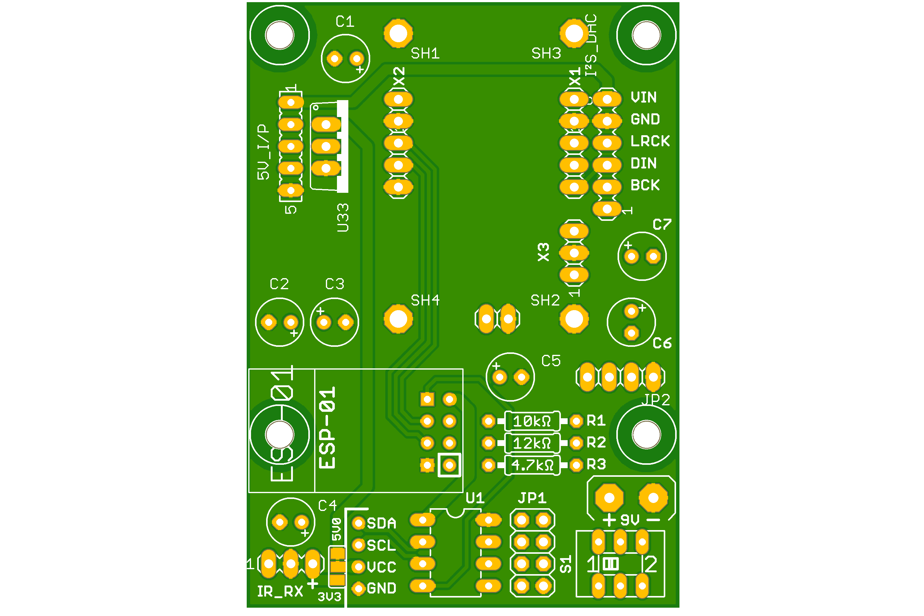
- // ESP-01 CONNECTIONs //
- // IO0 - SDA
- // IO2 - SCL
- // RX - IR Rx I/P
- // RST - 10kΩ-/\/\/\- 3V3
- // EN - 12kΩ-/\/\/\- 3V3
- // 3V3 - 3V3
- // GND - GND
- // TX - 4.7kΩ-/\/\/\- 3V3 [UNUSED]-AVAILABLE FOR FUTURE USE
- // EEPROM AT24C02 or AT24C04
For best audio experience we need to connect the I2S DAC audio output to external self-powered speaker.
The I2S output FM Radio was extensively tested with following DACs and Amplifier boards

Comments