


Hardware components | ||||||
 |
| × | 1 | |||
 |
| × | 1 | |||
 |
| × | 1 | |||
 |
| × | 1 | |||
 |
| × | 1 | |||
 |
| × | 1 | |||
 |
| × | 2 | |||
Software apps and online services | ||||||
 |
| |||||
Hand tools and fabrication machines | ||||||
 |
| |||||
 |
| |||||
An electronic codelock is a security device that grants access using a numerical sequence—a PIN code—rather than a traditional physical key. These systems are common in offices, apartment complexes, and increasingly, modern "smart" homes.
In some of my previous videos, I described several different ways to make a simple electronic codelock. This time I will show you how I developed and built a prototype for a real code-lock, which in its characteristics is much more advanced than many commercial devices of this kind.
The test prototype contains a real mechanical lock with standard dimensions. During the development, I gradually solved the problems one by one. I decided to use standard components that are easily available on the market and are relatively inexpensive.
Here is what the mechanical-electronic part looks like, made on a plastic board for greater visibility and easy modification if necessary during development.
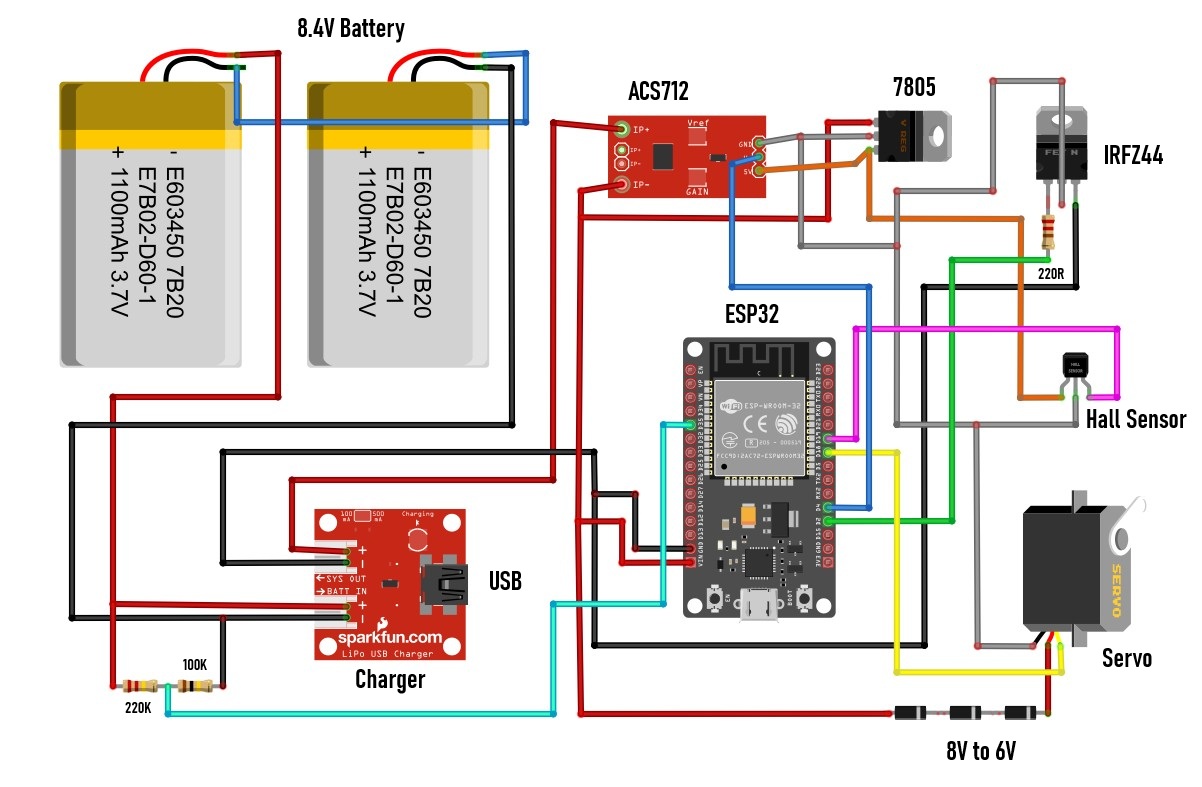
I'll start with the electronic components:
- And finally, the motor that moves the key in the lock. In this prototype, I use a small, cheap servo modified in a way that it can move continuously in any direction. We will not dwell on the method of modification here because it is explained in detail in many videos and the procedure is relatively easy. I chose this particular way of moving the lock because of its universality. If in the final product we use a larger servo with metal gears, then there is no need for any changes to the code, but also with minimal changes, a brushless motor with a bidirectional driver, or a regular motor with an H-bridge driver can be used.
- I also made a special bearing for the lock, so that the motor can move the key left and right, so that we have approximately realistic conditions during testing.
- Otherwise, all this electronics, using SMD components, can be placed on a PCB slightly larger than an MCU dev board.
Now let's move on to the software part. The code is made in a way that almost every phase of the lock's operation can be changed at the very beginning without having to walk through the entire code.
This is a crucial requirement in this type of development project, because very often when testing and changing components, quick changes need to be made to the code. I will describe all the variables that can be changed directly, as well as their functions in the circuit:
- At the beginning, all 5 pins of the ESP32 used in this project are defined.
- Then comes the interval at which data about the battery status is sent.
- Offset is the value at which the servo stops when no movement command is sent. This value depends on the accuracy of the two resistors that are built into the modified servo.
- With S-U and S-L the speed of movement of the servo during Unlocking and Locking is defined.
- IGNORE_TIME is the time during which the Hall sensor is turned off when sending a command to the motor. Specifically, if this variable is 0, the motor will never start.
- SOFT_START_TIME is the time after which the motor will start moving. This allows current peaks during motor start-up to not be measured, which could give a false alarm for a stalled motor.
- BRAKE_PULSE defined in microseconds is used for fine tuning so that the magnet should stop exactly under the HOME hall sensor. This "brake" value is determined purely experimentally and depends on the motor used.
- CURRENT_LIMIT is the current value in milliamperes above which the motor is signaled to be stalled and a command to shut it down is sent.
- To avoid false alarms for a stalled motor, it is stopped only if there is a certain number of consecutive measurements above the previously set current limit. This number of consecutive measurements is defined by STALL_SAMPLES.
- Finally, float vZero is used for calibration to display the correct battery voltage value.
For access control and password entry, I use a smartphone with an Android application, which by the way is my first Android application. It probably could have been done much more professionally, but that wasn't my primary goal in this case, but rather a way to have full control over the lock. When activating the application, a field for entering a pin appears, which is the simplest possible protection.
I mentioned earlier that this is my first Android application and I did not intend to waste a lot of time on its implementation. Otherwise, the security part is extremely important in this project, so multiple priorities and levels of protection should be implemented in the final product. By entering the correct pin, we enter the main menu:
First, the application connects to the lock via BLE connection. Here, the status of the lock (locked or unlocked) is displayed and below it, the state of the battery, which is an integral part of the lock. The state of the battery is accompanied by corresponding different colors. In the middle of the screen, there is a large round button with which we unlock or lock the door. This is the basic user menu and should be enough in 99% of cases when using the code lock. However, sometimes it can happen that the lock gets stuck, or we want to change the number of turns when locking/unlocking. For this purpose, there is another SETTINGS button that enters the next menu.
There we have the opportunity to first change the number of turns of the key - one (default) or two as desired. This setup becomes active after exiting the settings screen. Then there are two more buttons marked L and R that are used for manual movement of the motor. This option is very useful in case the key gets stuck, because manual movement is defined in the code in such a way that the servo turns with the greatest force and the current sensor is bypassed. Next comes the most interesting part, and that is how this device behaves in approximately real conditions. I say approximately because what is missing here is the locking/unlocking mechanism that is mounted inside the door. However, today's locks are very precisely made so that only a little more force is needed to move that mechanism. Also, let's not forget that the final product would use a servo that is many times stronger and of higher quality than this $1 serv
Next comes the most interesting part, and that is how this device behaves in approximately real conditions. I say approximately because what is missing here is the locking/unlocking mechanism that is mounted inside the door. However, today's locks are very precisely made so that only a little more force is needed to move that mechanism. Also, let's not forget that the final product would use a servo that is many times stronger and of higher quality than this $1 servo.
Demonstration
Now I will connect an Ammeter to see the total consumption of the device when it is idle. This is actually, besides functionality, the primary goal - to achieve as little consumption as possible when the device is not in use. The duration of the batteries on a single charge depends on this.
It can be seen that the idle consumption is about 30 mA, seemingly little, but in fact this is a huge value for this type of device. The code includes Light Sleep mode - a compromise between Deep Sleep mode and a normally active MCU. The difference between Light Sleep and Deep Sleep is a few milliamperes, but in Light Sleep mode, connecting to BLE is almost instant, unlike Deep Sleep where it can take tens of seconds or more, which would not be practical at all. Currently, the largest energy consumer is this linear regulator located on the MCU board and which reduces the input voltage from 8V to 3.3V required for normal operation of the ESP32. If I replace this linear regulator with a switching mode regulator (unfortunately, I don't have one at hand at the moment), the total consumption will be reduced to 3 to 5 mA, which is the absolute minimum for the device to function normally with this hardware.
It can be seen that the idle consumption is about 30 mA, seemingly little, but in fact this is a huge value for this type of device. The code includes Light Sleep mode - a compromise between Deep Sleep mode and a normally active MCU. The difference between Light Sleep and Deep Sleep is a few milliamperes, but in Light Sleep mode, connecting to BLE is almost instant, unlike Deep Sleep where it can take tens of seconds or more, which would not be practical at all. Currently, the largest energy consumer is this linear regulator located on the MCU board and which reduces the input voltage from 8V to 3.3V required for normal operation of the ESP32. If I replace this linear regulator with a switching mode regulator (unfortunately, I don't have one at hand at the moment), the total consumption will be reduced to 3 to 5 mA, which is the absolute minimum for the device to function normally with this hardware.
So with all the hardware and software modifications to save power, the average battery would last a maximum of about a week with normal use of the lock. However, it is known that such locks from well-known brand manufacturers can work for three to six months on a single battery charge. The secret is in the use of highly specialized chips designed specifically for such battery-powered devices. One of the manufacturers of such chips intended for industrial use is Nordic Semiconductors, whose specialized chips have several thousand times lower power consumption than, for example, ESP32 in Deep Sleep mode. These chips practically do not consume any power when in standby mode. However, these industrial chips use a special framework developed by the manufacturer, and the way they are programmed is characteristic and different for each series.
And finally, a short conclusion. With this project, you could roughly see how complex and time-consuming the development of a device is, before it reaches commercial production. In particular, this code lock, despite all the measures taken, especially for energy saving, does not meet the standards for a battery-powered device of this type, but it is certainly an excellent basis for further development with specialized chips, taking into account that the programming logic remains exactly the same.


_3u05Tpwasz.png?auto=compress%2Cformat&w=40&h=40&fit=fillmax&bg=fff&dpr=2)
Comments