


Hardware components | ||||||
| × | 1 | ||||
 |
| × | 1 | |||
 |
| × | 1 | |||
 |
| × | 1 | |||
 |
| × | 1 | |||
Software apps and online services | ||||||
 |
| |||||
Hand tools and fabrication machines | ||||||
 |
| |||||
 |
| |||||
These days I accidentally came across this small retro Black and White TV with a built-in Radio, so I immediately decided to make some simple useful device with it. Of course, first I decided to check its current condition and functionality.
Let's examine the Radio receiver. As far as I can see, this part of the device is functioning normally and the only thing that needs to be cleaned is the volume potentiometer, possibly with some contactor spray.
Now let's move on to the TV receiver. In a few seconds, a white raster appears on the screen, which is a sign that this part of the device is probably completely functional. We still have to examine the tuner part, by bringing an analog signal to the antenna input. For this purpose, I will use the signal from cable television. This signal is in the VHF-III Band, so now I will start searching for channels.
As I assumed, and the TV receiver is completely functional, but unfortunately nowadays it has no significant use value except as part of some retro TV collection.
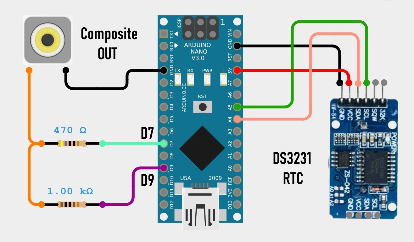
I got the idea to "bring back to life" this small cute device in a way that I would make some kind of clock that would display the time and date on the screen. And of course the most suitable for that purpose is the Arduino microcontroller together with the TVout library with the help of which a composite signal is generated through only two resistors.
The model of this device is "Inno-Hit TV128" but after a long search I was unable to find any service manual or circuit diagram. Many years ago I worked in a TV repair shop and I have relatively extensive knowledge in this area.
This project is sponsored by PCBWay . From September 1st 2025 to 31st Januarry 2026 PCBWay organize the 8th Priject Design Contest. All interested participants can compete in three categories: Electronic Project, Mechanical Project or AIoT Project. The best projects will receive valuable prizes in cash, value cupons and developement boards. Don't miss this unique opportunity and submit your project as soon as possible. PCBWay has all the services you need to create the project at the Best price.
By definition the composite input should be located somewhere between the video amplifier and the sync section. After a detailed examination of the PCB and its components I discovered that the video amplifier in this case is TA7678AP IC and the sync section is µPC1379C IC.
After several hours of experimentation I discovered that the composite input is located right after the video output from TA7678AP IC. That video signal passes through this jumper J112..
So I need to remove this jumper so that the previous tuner circuit does not affect the signal, and connect the composite input directly to the input of the sync section.
Composite signal generator consisting of an Arduino Nano and 2 resistors, and there is also the DS3231 real time clock module with a built-in battery from which the exact time is read and displayed on the TV screen.
Now for testing I will send a demo signal, actually an example from the TVout library. One important note. If you install the TVout library by default via "manage libraries" or by copying it to the library folder, you will get the error "fontALL.h: No such file or directory" when compiling.
To avoid this, we need to install the two libraries "TVout" and "TVoutfonts" separately, which are given at the end of the text.
Now let's start testing. We bring the composite signal generated by the Arduino to the appropriate input which is connected in the manner explained previously. The switch should be in the "Composite" position. The content is clearly displayed on the screen.
The code is mainly based on the TVout library so my goal was to introduce several different possibilities such as drawing Logos, rectangles, lines, text borders, as well as black text on a white background.
The exact time and date are read from the DS3231 Realtime Clock module which also has a built-in battery to save time when there is no power.
Otherwise, when modifying the TV, I installed a small switch that allows you to choose between standard TV mode and composite video mode.
And finally, a short conclusion. This project successfully transforms a vintage TV into a functional and stylish retro clock. It's a perfect fusion of classic hardware and modern microcontroller simplicity. Also, modifying the small TV without any documentation or schematics was a big challenge for me.


Comments