

Hardware components | ||||||
 |
| × | 1 | |||
| × | 1 | ||||
 |
| × | 1 | |||
 |
| × | 1 | |||
Software apps and online services | ||||||
 |
| |||||
Hand tools and fabrication machines | ||||||
 |
| |||||
 |
| |||||
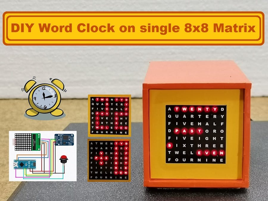
This time I will show you how to make a beautiful small Word Clock. On this type of clock, the current time is displayed in the form of words, instead of numbers as in the classic clock.
The construction of such a device is usually complex in the part of making a suitable box with partitions for each individual LED, and the clock face that should be made with a special printer or Laser cutter. In this case, the construction is completely simplified by using an 8 by 8 matrix driven by the MAX7219 chip, and the clock face is printed with a laser printer on a plain sheet of paper. Also, instead of this small matrix, we can place a larger one with dimensions of 6 by 6 cm. I used this type of matrix where the driver board is much larger than the matrix, so I removed the board from the matrix and set it aside.
The code is the work of Marco Colli and the curiosity is that he is also the creator of all the libraries needed for this project. The code, as well as the libraries, can be downloaded from its GitHub: https://github.com/MajicDesigns.
As I mentioned before, the device is extremely simple to make, and you can make it in less than half an hour without a box.
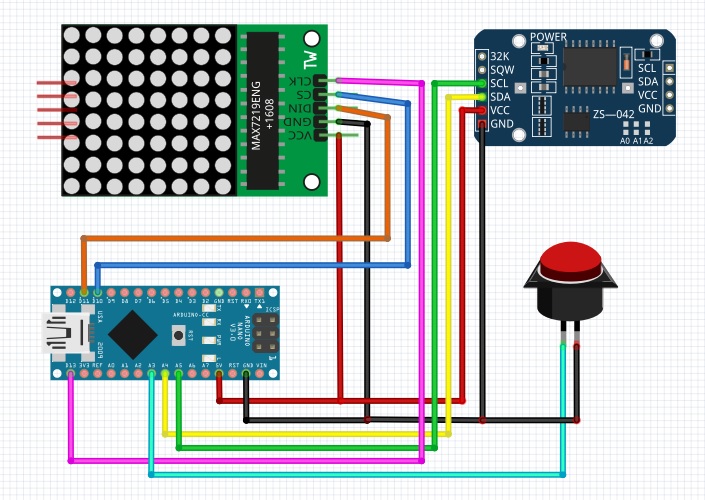
It consists of only a few components:
- Arduino nano microcontroller
- 8 by 8 matrix module with MAX7219 driver
- DS3231 realtime clock module
- and one Button
By the way, I used the box from one of my previous projects, so I used the button from the rotating encoder.
Immediately after switching on, we can read the exact time in word form. Let me emphasize that the tolerance, in this case, is a maximum of +/- 5 minutes of real time which is a consequence of the small number of LEDs, in fact, they are letters, but that is the price of the simplicity of construction. However, we have the option to read the exact time in the form of large numbers and this is achieved with a short click of the button.
Rather than change the clock time for the Summer Time period, a long press of the switch will set up an automatic +1 hour offset when displaying the current time. Summer Time offset is reset to 0 by another long press.
To set up the time:
- Double click the switch
- Then click to progress the hours
- Double click to stop editing hours and edit minutes
- Then click to progress the minutes
- Double click to exit editing and set the new time
Finally, the radio is mounted in a suitable box made of PVC and coated with self-adhesive wallpaper.
// Program to implement a Word Clock using the MD_MAX72XX library.
// by Marco Colli
//
// April 2016 - version 1.0
// - Initial release
//
// April 2017 - version 1.1
// - Added summer time auto adjustment (long press)
//
// June 2019 - version 1.2
// - Changed for new MD_MAX72xx library hardware definition
//
// Description:
// ------------
// The word clock 8x8 LED matrix module to shine light through a
// word mask printed on paper. The mask is placed over the matrix
// LEDs, folding over the small flaps on the sides and attaching them
// to the side of the matrix using double sided tape.
//
// The clock face (word matrix) for the clock can be found in the doc
// folder of this sketch (Microsoft Word document and PDF versions).
//
// Additional hardware required is RTC clock module (DS3231 used here)
// and a momentary-on switch (tact switch or similar).
//
// More information on the Word Clock can be found in the blog article at
// https://arduinoplusplus.wordpress.com/2016/04/24/max7219-led-matrix-module-mini-word-clock/
//
// Functions:
// ----------
// - To see the time in digits, press the mode switch once.
// - To set up the time:
//   + Double click the mode switch
//   + Then click to progress the hours
//   + Double click to stop editing hours and edit minutes
//   + Then click to progress the minutes
//   + Double click to exit editing and set the new time
// Setup mode has a timeout for no inactivity. On exit it sets the new time
// and returns to normal word display.
//
// Library dependencies:
// ---------------------
// MD_DS1307 and MD_DS3231 RTC libraries found at https://github.com/MajicDesigns/DS1307
// and https://github.com/MajicDesigns/DS3231. Any other RTC may be
// substitiuted with few changes as the current time is passed to all
// matrix display functions.
//
// MD_MAX72xx library can be found at https://github.com/MajicDesigns/MD_MAX72XX
// MD_KeySwitch library is found at https://github.com/MajicDesigns/MD_KeySwitch
//

#include <SPI.h>
#include <Wire.h>       // I2C library for RTC
#include <EEPROM.h>     // for saving summer time status
#include <MD_MAX72xx.h>
#include <MD_KeySwitch.h>
#include <MD_DS3231.h>

// --------------------------------------
// Hardware definitions
// NOTE: For non-integrated SPI interface the pins will probably
// not work with your hardware and may need to be adapted.
const uint8_t CLK_PIN = 13;  // (or SCK) connect to matrix CLK
const uint8_t DATA_PIN = 11; // (or MOSI) connect to matrix DATA
const uint8_t CS_PIN = 10;   // (or SS) connect to matrix LOAD

const uint8_t MODE_SW_PIN = 3; // setup pin connected to mode switch

const uint8_t EE_SUMMER_FLAG = 0;

// --------------------------------------
// Miscelaneous defines
const uint8_t   CLOCK_UPDATE_TIME = 5;  // in seconds - time resolution to nearest 5 minutes does not need rapid updates!
const uint32_t  SHOW_DELAY_TIME = 1000; // in millisecnds - how long to show time in digits
const uint32_t  SETUP_TIMEOUT = 10000;  // in milliseconds - timeout for setup mode

// --------------------------------------
//  END OF USER CONFIGURABLE INFORMATION
// --------------------------------------

#define DEBUG 0

// --------------------------------------
// Enumerated types for state machines
typedef enum stateRun_t { SR_UPDATE, SR_IDLE, SR_SETUP, SR_TIME, SR_SUMMER_TIME };
typedef enum stateSetup_t { SS_DISP_HOUR, SS_HOUR, SS_DISP_MIN, SS_MIN, SS_END };

// --------------------------------------
// Global variables
MD_KeySwitch  swMode(MODE_SW_PIN);            // mode/setup switch handler
MD_MAX72XX    clock = MD_MAX72XX(MD_MAX72XX::FC16_HW, CS_PIN, 1);  // SPI hardware interface

//MD_MAX72XX clock = MD_MAX72XX(MD_MAX72XX::FC16_HW, DATA_PIN, CLK_PIN, CS_PIN, 1); // Arbitrary pins

#define ARRAY_SIZE(a) (sizeof(a)/sizeof(a[0]))

#if  DEBUG
#define PRINT(s, x) { Serial.print(F(s)); Serial.print(x); }
#define PRINTS(x) Serial.print(F(x))
#define PRINTD(x) Serial.println(x, DEC)
#else
#define PRINT(s, x)
#define PRINTS(x)
#define PRINTD(x)
#endif

// --------------------------------------
// Font data used to set the time on the clock.
// The characters are 4 pixels wide so that 2 can fit on the display by shifting
// the data for the leftmost character and 'OR'ing in the rightmost character.
// Font data is stored in display rows.

const uint8_t FONT_ROWS = 8;

const PROGMEM uint8_t fontMap[][FONT_ROWS] =
{
  { 0x7, 0x5, 0x5, 0x5, 0x5, 0x5, 0x7, 0x0 }, // 0
  { 0x1, 0x1, 0x1, 0x1, 0x1, 0x1, 0x1, 0x0 }, // 1
  { 0x7, 0x1, 0x1, 0x7, 0x4, 0x4, 0x7, 0x0 }, // 2
  { 0x7, 0x1, 0x1, 0x7, 0x1, 0x1, 0x7, 0x0 }, // 3
  { 0x4, 0x4, 0x5, 0x5, 0x7, 0x1, 0x1, 0x0 }, // 4
  { 0x7, 0x4, 0x4, 0x7, 0x1, 0x1, 0x7, 0x0 }, // 5
  { 0x7, 0x4, 0x4, 0x7, 0x5, 0x5, 0x7, 0x0 }, // 6
  { 0x7, 0x1, 0x1, 0x1, 0x1, 0x1, 0x1, 0x0 }, // 7
  { 0x7, 0x5, 0x5, 0x7, 0x5, 0x5, 0x7, 0x0 }, // 8
  { 0x7, 0x5, 0x5, 0x7, 0x1, 0x1, 0x7, 0x0 }, // 9

  { 0x0, 0x0, 0x2, 0x7, 0x2, 0x0, 0x0, 0x0 }, // +
  { 0x0, 0x0, 0x0, 0x7, 0x0, 0x0, 0x0, 0x0 }, // -
};

// --------------------------------------
// Define the data for the words on the clock face.
// The clock face has the following letter matrix
// 7 6 5 4 3 2 1 0  <-- column
// A T W E N T Y D  <-- row 0
// Q U A R T E R Y  <-- row 1
// F I V E H A L F  <-- row 2
// D P A S T O R O  <-- row 3
// F I V E I G H T  <-- row 4
// S I X T H R E E  <-- row 5
// T W E L E V E N  <-- row 6
// F O U R N I N E  <-- row 7
//
// - Minutes to/past the hour are all in the rows 0-2 of the display.
// - Past/to text is on row 3
// - The hour name is in rows 4-7
//
// The words may be defined in one or more rows. So to define the bit
// pattern to illuminate for a word, just need to know the row number(s)
// and the bit pattern(s) to turn on for that row.
typedef struct clockWord_t
{
  uint8_t row;
  uint8_t data;
};

// Minutes and to/past are always on the same row, so they can be defined as
// individual elements.
const PROGMEM clockWord_t M_05 = { 2, 0b11110000 };
const PROGMEM clockWord_t M_10 = { 0, 0b01011000 };
const PROGMEM clockWord_t M_15 = { 1, 0b11111110 };
const PROGMEM clockWord_t M_20 = { 0, 0b01111110 };
const PROGMEM clockWord_t M_30 = { 2, 0b00001111 };

const PROGMEM clockWord_t TO = { 3, 0b00001100 };
const PROGMEM clockWord_t PAST = { 3, 0b01111000 };

// Some hour names are split across rows, so use more than one definition
// per word - make them all arrays for consistent handling in loop code.
//const PROGMEM clockWord_t H_01[] = { { 7, 0b01000011 } }; // 1-2 option
const PROGMEM clockWord_t H_01[] = { { 7, 0b01001001 } }; // 1-1-1 symmetrical option
const PROGMEM clockWord_t H_02[] = { { 6, 0b11000000 }, { 7, 0b01000000 } };
const PROGMEM clockWord_t H_03[] = { { 5, 0b00011111 } };
const PROGMEM clockWord_t H_04[] = { { 7, 0b11110000 } };
const PROGMEM clockWord_t H_05[] = { { 4, 0b11110000 } };
const PROGMEM clockWord_t H_06[] = { { 5, 0b11100000 } };
const PROGMEM clockWord_t H_07[] = { { 5, 0b10000000 }, { 6, 0b00001111 } };
const PROGMEM clockWord_t H_08[] = { { 4, 0b00011111 } };
const PROGMEM clockWord_t H_09[] = { { 7, 0b00001111 } };
//const PROGMEM clockWord_t H_10[] = { { 6, 0b10000011 } };  // 1-2 horizontal option
//const PROGMEM clockWord_t H_10[] = { { 6, 0b10001001 } }; // 1-1-1 horizontal option
const PROGMEM clockWord_t H_10[] = { { 4, 0b00000001 }, { 5, 0b00000001 }, { 6, 0b00000001 } };   // vertical option
const PROGMEM clockWord_t H_11[] = { { 6, 0b00111111 } };
const PROGMEM clockWord_t H_12[] = { { 6, 0b11110110 } };

// --------------------------------------
// Code
bool isSummerMode()
// Return true if summer mode is active
{
  return(EEPROM.read(EE_SUMMER_FLAG) != 0);
}

uint8_t currentHour(uint8_t h)
// Change the RTC hour to include any summer time offset
// Clock always holds the 'real' time.
{
  h += (isSummerMode() ? 1 : 0);
  if (h > 12) h = 1;

  return(h);
}

void dumpTime()
// Show displayed time to the debug display
{
  uint8_t h = currentHour(RTC.h);

  if (h < 10) PRINTS("0");
  PRINT("", h);
  PRINTS(":");
  if (RTC.m < 10) PRINTS("0");
  PRINT("", RTC.m);
  PRINTS(":");
  if (RTC.s < 10) PRINTS("0");
  PRINT("", RTC.s);
  PRINTS(" ");
}

void mapOffset(uint8_t *map, int8_t num)
// *map is a pointer to a FONT_ROWS byte buffer to capture the
// rows of the mapped number, num is the offset single digit
{
  uint8_t sign = (num >= 0 ? 10 : 11); // 10th font char map is for a '+', the 11th for a '-'.

  num = abs(num) % 10;  // positive single digit

  for (uint8_t i = 0; i < FONT_ROWS; i++)
  {
    *map = pgm_read_byte(&fontMap[sign][i]) << 4;
    *map |= pgm_read_byte(&fontMap[num][i]);
    map++;
  }
}

void mapNumber(uint8_t *map, uint8_t num)
// *map is a pointer to a FONT_ROWS byte buffer to capture the
// rows of the mapped number, num is the decimal number to convert
{
  uint8_t hi = num / 10;
  uint8_t lo = num % 10;

  for (uint8_t i = 0; i < FONT_ROWS; i++)
  {
    *map = pgm_read_byte(&fontMap[hi][i]) << 4;
    *map |= pgm_read_byte(&fontMap[lo][i]);
    map++;
  }
}

void mapShow(uint8_t *map)
// *map is a pointer to a FONT_ROWS byte buffer to display on the
// clock face.
{
  clock.control(MD_MAX72XX::UPDATE, MD_MAX72XX::OFF);
  clock.clear();

  for (uint8_t i = 0; i < FONT_ROWS; i++)
    clock.setRow(i, *map++);

  clock.control(MD_MAX72XX::UPDATE, MD_MAX72XX::ON);
}

void setupTime(uint8_t &h, uint8_t &m)
// Handle the user interface to set the current time.
// Remains in this function until completed.
{
  uint32_t  timeLastActivity = millis();
  uint8_t map[FONT_ROWS];
  stateSetup_t state = SS_DISP_HOUR;

  while (state != SS_END)
  {
    // check if we time out
    if (millis() - timeLastActivity >= SETUP_TIMEOUT)
    {
      PRINTS("\nSetup inactivity timeout");
      state = SS_END;
    }

    // process current state
    switch (state)
    {
    case SS_DISP_HOUR:   // show the hour
      mapNumber(map, currentHour(RTC.h));
      mapShow(map);
      state = SS_HOUR;
      break;

    case SS_HOUR:   // handle setting hours
      switch (swMode.read())
      {
      case MD_KeySwitch::KS_DPRESS:   // move on to minutes
        timeLastActivity = millis();
        state = SS_DISP_MIN;
        break;
      case MD_KeySwitch::KS_PRESS:    // increment the hours
        timeLastActivity = millis();
        h++;
        if (h == 13) h = 1;
        state = SS_DISP_HOUR;
        break;
      }
      break;

    case SS_DISP_MIN:   // show the minutes
      mapNumber(map, m);
      mapShow(map);
      state = SS_MIN;
      break;

    case SS_MIN:   // handle setting minutes
      switch (swMode.read())
      {
      case MD_KeySwitch::KS_DPRESS:   // move on to end
        timeLastActivity = millis();
        state = SS_END;
        break;
      case MD_KeySwitch::KS_PRESS:    // increment the minutes
        timeLastActivity = millis();
        m = (m + 1) % 60;
        state = SS_DISP_MIN;
        mapShow(map);
        break;
      }
      break;

    default:  // our work is done
      state = SS_END;
    }
  }
}

void flipSummerMode(void)
// Reverse the the summer flag mode in the EEPROM
{
  uint8_t map[FONT_ROWS];

  // handle EEPROM changes
  EEPROM.write(EE_SUMMER_FLAG, isSummerMode() ? 0 : 1);
  PRINT("\nNew Summer Mode ", isSummerMode());

  // now show the current offset on the display
  mapOffset(map, (isSummerMode() ? 1 : 0));
  mapShow(map);
  delay(SHOW_DELAY_TIME);
}

void showTime(uint8_t h, uint8_t m)
// Display the current time in digits on the matrix.
// Remains in this function until completed.
{
  uint8_t map[FONT_ROWS];

  mapNumber(map, h);
  mapShow(map);
  delay(SHOW_DELAY_TIME);
  mapNumber(map, m);
  mapShow(map);
  delay(SHOW_DELAY_TIME);
}

void updateClock(uint8_t h, uint8_t m)
// Work out what current time it is in words and turn on the right
// parts of the display. The time is passed to the function so that
// it is dependent of the time source.
// This logic tries to copy the approximations people make when reading
// analog time. It is consistent but arbitrary - note that any changes need
// to be made consistently across all the checks in this part of the code.
{
  const uint8_t PRE_DELTA = 2;    // minutes before the actual min
  const uint8_t POST_DELTA = 2;   // minutes after the actual min

  const clockWord_t *H;
  uint8_t numElements;

  PRINTS("\nT: ");
  dumpTime();  // debug output only

  // freeze the clock display while we make changes to the matrix
  clock.control(MD_MAX72XX::UPDATE, MD_MAX72XX::OFF);
  clock.clear();

  // minutes -  are worked out in an interval [-PRE_DELTA, POST_DELTA] around the time
  // to select the choice of words.
  switch (m)
  {
  case 0 ... 0+POST_DELTA:
  case 60-PRE_DELTA ... 59:
    // nothing to say at top of the hour
    break;

  case 5-PRE_DELTA ... 5+POST_DELTA:
  case 55-PRE_DELTA ... 55+POST_DELTA:
    PRINTS("FIVE");
    clock.setRow(pgm_read_byte(&M_05.row), pgm_read_byte(&M_05.data));
    break;

  case 10-PRE_DELTA ... 10+POST_DELTA:
  case 50-PRE_DELTA ... 50+POST_DELTA:
    PRINTS("TEN");
    clock.setRow(pgm_read_byte(&M_10.row), pgm_read_byte(&M_10.data));
    break;

  case 15-PRE_DELTA ... 15+POST_DELTA:
  case 45-PRE_DELTA ... 45+POST_DELTA:
    PRINTS("QUARTER");
    clock.setRow(pgm_read_byte(&M_15.row), pgm_read_byte(&M_15.data));
    break;

  case 20-PRE_DELTA ... 20+POST_DELTA:
  case 40-PRE_DELTA ... 40+POST_DELTA:
    PRINTS("TWENTY");
    clock.setRow(pgm_read_byte(&M_20.row), pgm_read_byte(&M_20.data));
    break;

  case 25-PRE_DELTA ... 25+POST_DELTA:
  case 35-PRE_DELTA ... 35+POST_DELTA:
    PRINTS("TWENTY-FIVE");
    clock.setRow(pgm_read_byte(&M_05.row), pgm_read_byte(&M_05.data));
    clock.setRow(pgm_read_byte(&M_20.row), pgm_read_byte(&M_20.data));
    break;

  case 30-PRE_DELTA ... 30+POST_DELTA:
    PRINTS("HALF");
    clock.setRow(pgm_read_byte(&M_30.row), pgm_read_byte(&M_30.data));
    break;
  }

  // To/past display
  if (m > 0+POST_DELTA && m < 60-PRE_DELTA)  // top of the hour interval displays the hour only
  {
    if (m <= 30+POST_DELTA)  // in the first half hour it is 'past' and ...
    {
      PRINTS(" PAST ");
      clock.setRow(pgm_read_byte(&PAST.row), pgm_read_byte(&PAST.data));
    }
    else    // ... after the half hour it becomes 'to'
    {
      PRINTS(" TO ");
      clock.setRow(pgm_read_byte(&TO.row), pgm_read_byte(&TO.data));
    }
  }

  // After the half hour we have also have to adjust the hour number!
  if (m > 30 + POST_DELTA)
  {
    if (h < 12) h++;
    else h = 1;
  }

  // hour - straight translation of nummber to data. However, the word can can
  // span more than one line so the data is set up in arrays.
  switch (currentHour(h))
    {
    case  1: H = H_01;  numElements = ARRAY_SIZE(H_01);  PRINTS("ONE");  break;
    case  2: H = H_02;  numElements = ARRAY_SIZE(H_02);  PRINTS("TWO");  break;
    case  3: H = H_03;  numElements = ARRAY_SIZE(H_03);  PRINTS("THREE");  break;
    case  4: H = H_04;  numElements = ARRAY_SIZE(H_04);  PRINTS("FOUR");  break;
    case  5: H = H_05;  numElements = ARRAY_SIZE(H_05);  PRINTS("FIVE");  break;
    case  6: H = H_06;  numElements = ARRAY_SIZE(H_06);  PRINTS("SIX");  break;
    case  7: H = H_07;  numElements = ARRAY_SIZE(H_07);  PRINTS("SEVEN");  break;
    case  8: H = H_08;  numElements = ARRAY_SIZE(H_08);  PRINTS("EIGHT");  break;
    case  9: H = H_09;  numElements = ARRAY_SIZE(H_09);  PRINTS("NINE");  break;
    case 10: H = H_10;  numElements = ARRAY_SIZE(H_10);  PRINTS("TEN");  break;
    case 11: H = H_11;  numElements = ARRAY_SIZE(H_11);  PRINTS("ELEVEN");  break;
    case 12: H = H_12;  numElements = ARRAY_SIZE(H_12);  PRINTS("TWELVE");  break;
    }
    for (uint8_t i = 0; i < numElements; i++)
      clock.setRow(pgm_read_byte(&H[i].row), pgm_read_byte(&H[i].data));

  // finally, update the display with new data
  clock.control(MD_MAX72XX::UPDATE, MD_MAX72XX::ON);
}

void setup()
{
#if  DEBUG
  Serial.begin(115200);
#endif
  PRINTS("\n[MD_MAX72XX_WordClock Demo]");

  clock.begin();
  clock.control(MD_MAX72XX::INTENSITY, 2 + (MAX_INTENSITY / 2));

  swMode.begin();
  swMode.enableRepeat(false);

  // turn the clock on to 12H mode and make sure it is running
  RTC.control(DS3231_12H, DS3231_ON);
  RTC.control(DS3231_CLOCK_HALT, DS3231_OFF);

  PRINT("\nSummer Mode ", isSummerMode());
}

void loop()
{
  static stateRun_t state = SR_UPDATE;
  static uint32_t timeLastUpdate = 0;

  switch (state)
  {
  case SR_UPDATE:   // update the display
    timeLastUpdate = millis();
    RTC.readTime();
    updateClock(RTC.h, RTC.m);
    state = SR_IDLE;
    break;

  case SR_IDLE:   // wait for ...
    // ... time to update the display or ...
    if (millis() - timeLastUpdate >= CLOCK_UPDATE_TIME * 1000UL)
      state = SR_UPDATE;

    // ... user input from mode switch
    switch (swMode.read())
    {
    case MD_KeySwitch::KS_DPRESS:    state = SR_SETUP; break;
    case MD_KeySwitch::KS_PRESS:     state = SR_TIME; break;
    case MD_KeySwitch::KS_LONGPRESS: state = SR_SUMMER_TIME; break;
    }
    break;

  case SR_SETUP:   // time setup
    setupTime(RTC.h, RTC.m);
    // write new time to the RTC
    RTC.s = 0;
    RTC.writeTime();
    PRINTS("\nNew T: ");
    dumpTime();
    state = SR_UPDATE;
    break;

  case SR_TIME:   // show time as digits
    showTime(currentHour(RTC.h), RTC.m);
    state = SR_UPDATE;
    break;

  case SR_SUMMER_TIME:  // handle the summer time selection
    flipSummerMode();
    state = SR_UPDATE;
    break;

  default:
    state = SR_UPDATE;
  }
}


Comments