

Hardware components | ||||||
 |
| × | 1 | |||
 |
| × | 1 | |||
| × | 1 | ||||
 |
| × | 1 | |||
 |
| × | 1 | |||
| × | 2 | ||||
| × | 1 | ||||
Software apps and online services | ||||||
 |
| |||||
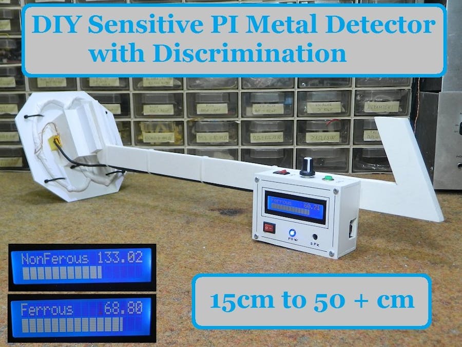
This time I will show you how to make a sensitive metal detector also capable of discriminating between ferrous and nonferrous materials. The sensitivity is satisfactory, given that it is a relatively simple device.
This project is sponsored by PCBgogo:
https://www.pcbgogo.com/promo/from_MirkoPavleskiMK
This is a continuation of David Crocker's project presented at the Arduino CC Forum in 2013. I decided to test its code because I did not find any evidence (Picture or video) that this metal detector was made by anyone and works well.
First I made a basic version with the code presented on GitHub, to make sure of the functionality of the device and then I upgraded the code so that it has an audible signal, and on a 16 on 2 LCD display visual information about the type of object detected (Ferrous or nonferrous material) and LCD bar graph for the proximity of detected objects.
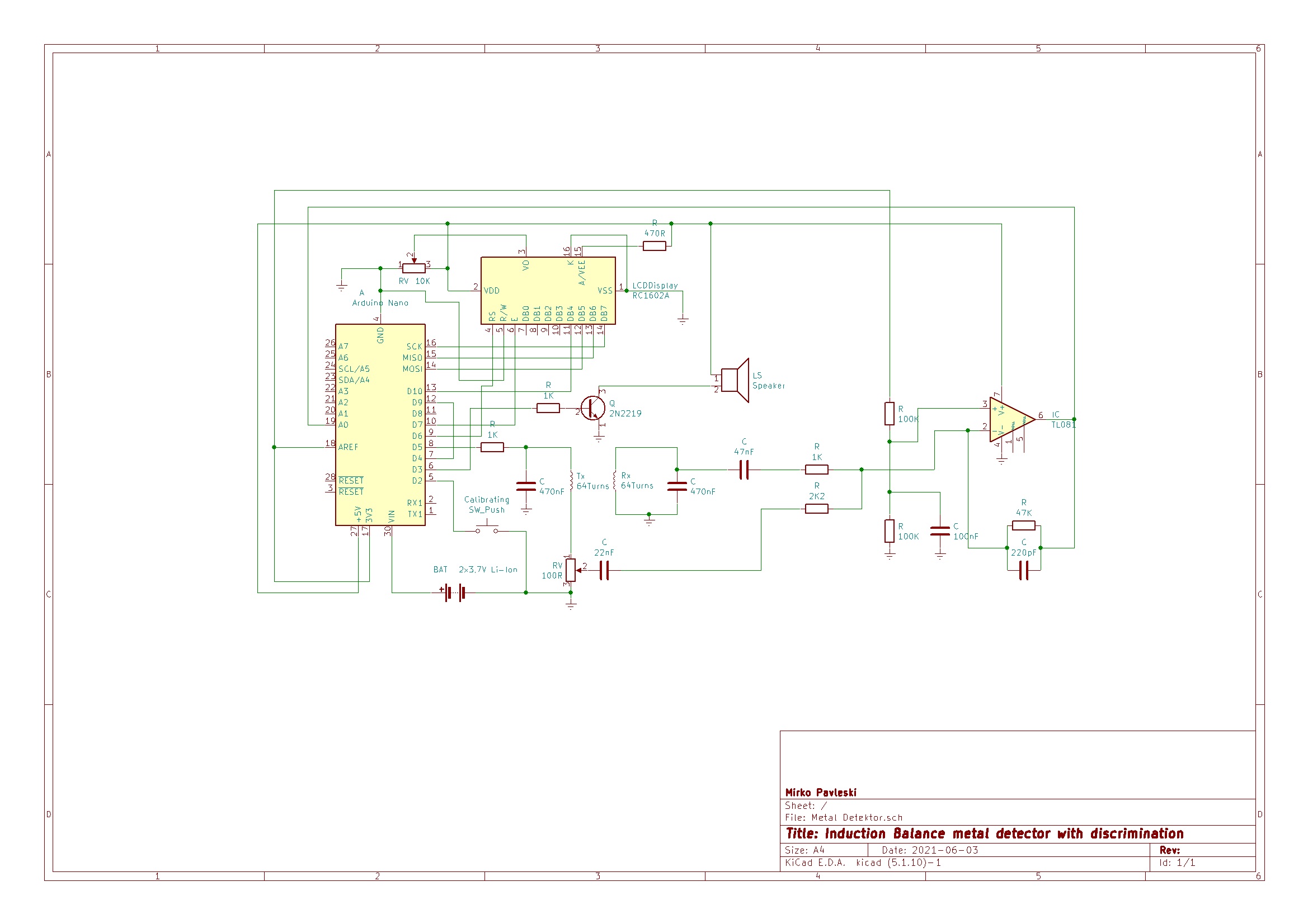
The device is very simple to build and consist of only a few components:
- Arduino Nano microcontroller
- Operational amplifier (in my case LT1677, but you can use TL081 or 741 )
- Few resistors and capacitors
- Small transistor and speaker
- LCD display
- 3 switches
- Potentiometer
- Battery
- And search coils
This is a VLF (very low frequency) Induction Balance detector technology and contains two identical coils : transmitter and receiver coil. As with all induction balance detectors, coil balance is very critical. The potentiometer is used to zero the small 90 degrees out-of-phase component of the signal. (the in-phase component is nulled by adjusting the relative placement of the coils in typical IB-detector style). Each of the coils is wound on 11cm body using 64 turns of 0.5mm^2 enameled copper wire in a D shape, wrapped tape around them, screened them using aluminum foil bound with tinned copper wire (taking care to leave a small gap so that the screen doesn’t behave like a shorted turn), and tie-wrapped them on to a plastic plate.
We first need to determine the parallel resonant frequency of the primary coil-capacitor circuit using one of the many online calculators. I measured it with an oscilloscope, but if you adhere to the dimensions given above, it will be exactly 7.64 kHz, so you can directly enter the value given in the code. In the case of another value of the resonant frequency, we need to make an appropriate change in the code in the queue:
#define TIMER1_TOP (249) // fine-tune the frequency
As you can see in the video, the results are surprisingly good. Without the presence of a metal, device is perfectly stable. The range is relatively large and for example, a metal cover with a diameter of 15 cm is detected at a distance of more than 30 cm. Larger metal objects are detected at distances greater than 40-50cm. We can detect a small coin at a distance of 15cm in the air. I use two lithium batteries for the power supply which are connected in series (7.4 volts) and this voltage is connected to the Vin input of the Arduino. Consumption does not exceed 20mA so batteries last a very long time. The video describes in detail the construction of the entire device.
These are only preliminary results. There is a possibility to significantly improve the sensitivity by inserting a power MOSFET transistor for driving the Tx coil, but I will test and present it in one of the following videos.


Comments