

Hardware components | ||||||
 |
| × | 1 | |||
 |
| × | 1 | |||
 |
| × | 1 | |||
 |
| × | 1 | |||
| × | 1 | ||||
Software apps and online services | ||||||
 |
| |||||
Hand tools and fabrication machines | ||||||
 |
| |||||
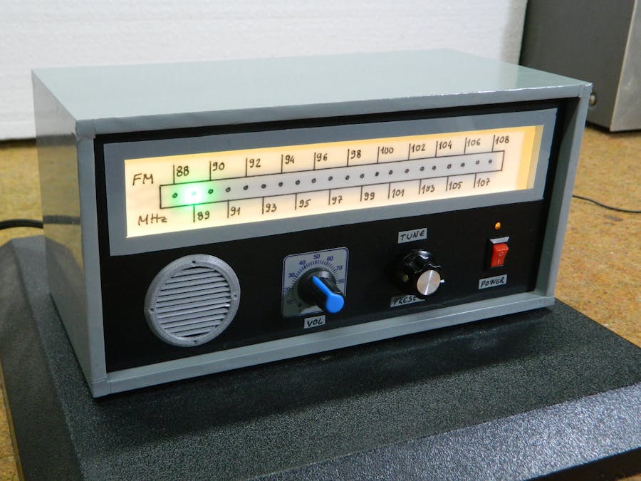
The device presented in the video is a standard FM Arduino radio but with an nice retro look. Contains a linear scale in which the frequency is displayed with an color LED dot which is an integral part of the WS2812 LED strip. There are several ways to select stations: standard with rotary encoder, predefined (memorized) stations in Code and auto dial (seek) function
The radio contains the following components:
-Arduino Nano microcontroller
-Si4703 cheap FM radio board
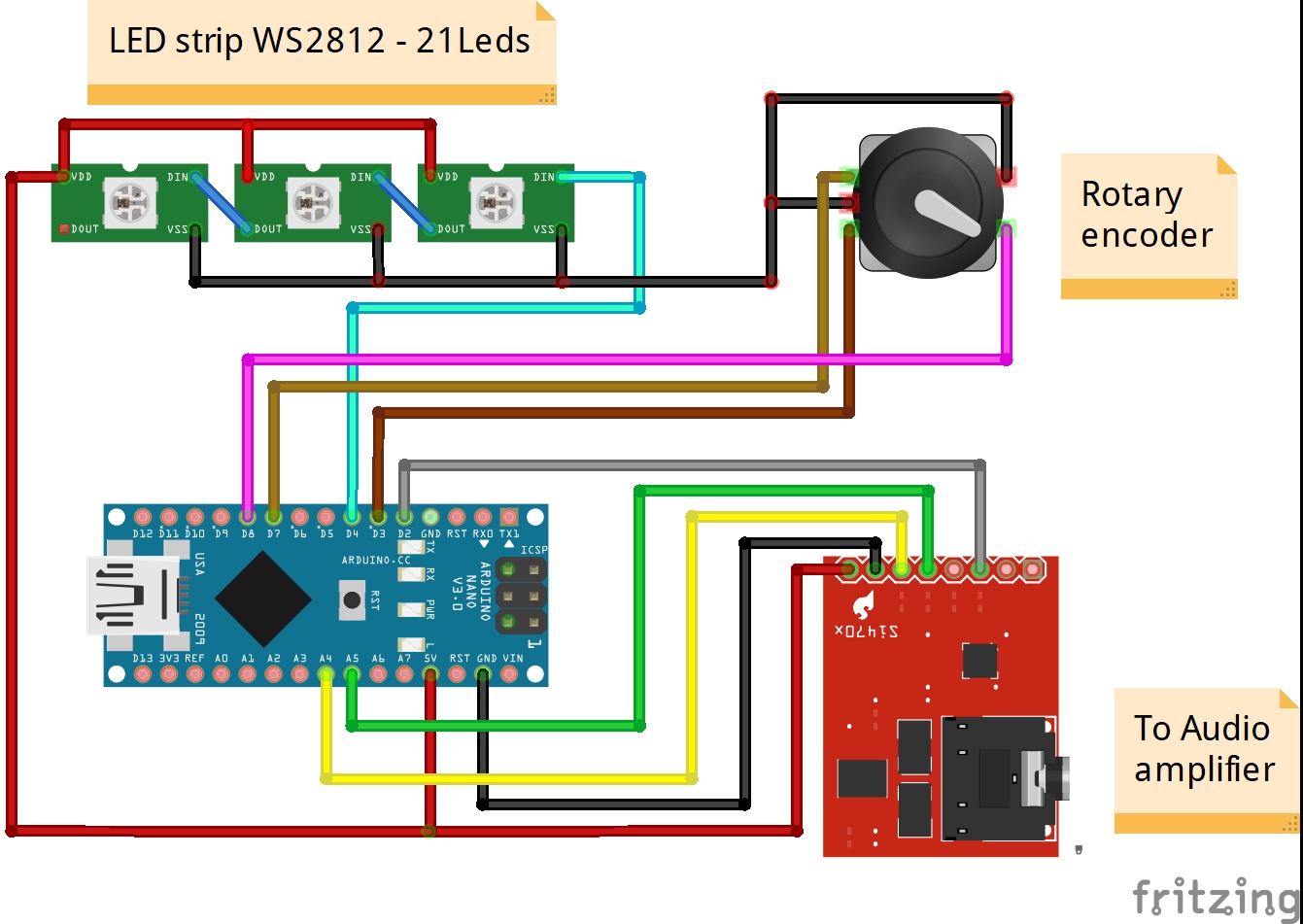
-WS2812 LED strip with 21 LEDs
-Small D-class audio amplifier board
-Speaker
-and rotary encoder
For the same hardware I will present you two different ways of working which are actually two different codes.
In the first case, the stations are selected manually using a rotary encoder which in this case simulates a variable capacitor. Also, in the code, we can redefine known radio station frequencies which we can select then by pressing the rotary encoder switch. We can actually "memorize" favorite stations. This time we will not talk about the sensitivity and selectivity of the receiver because our focus is the unusual scale with a retro look. Anyway the features are limited by the radio chip that is used.
In the second case we have automated station dialing using the seek function. This function is activated by briefly turning the encoder left or right. A blue LED blinking indicates a dialing, a green LED is for a mono station received and a red LED is for a stereo station received. The codes are taken from the Franz-Josef Haffner blog, and I made small modifications to the number of LEDs in the bar, Brightness of LEDs and the sensitivity threshold for radio signal detection in the second code. On his blog you can see a large number of old radios modified in different ways.
And now a few words about the making. The Si4703 is powered by 3.3V, so a level shifter between it and the Arduino Nano is required. As you can see in the diagram I did not use a level shifter, but not because it is so correct, but because I did not have it at the moment. Surprisingly, the device works quite normally without this part.
Finally, I placed the whole device in a suitable retro-look housing made of 5mm PVC and then coated with a self-adhesive label. At the end of the video you can follow the method of making this radio.


_3u05Tpwasz.png?auto=compress%2Cformat&w=40&h=40&fit=fillmax&bg=fff&dpr=2)
Comments