

Hardware components | ||||||
| × | 1 | ||||
| × | 1 | ||||
| × | 2 | ||||
_ztBMuBhMHo.jpg?auto=compress%2Cformat&w=48&h=48&fit=fill&bg=ffffff) |
| × | 1 | |||
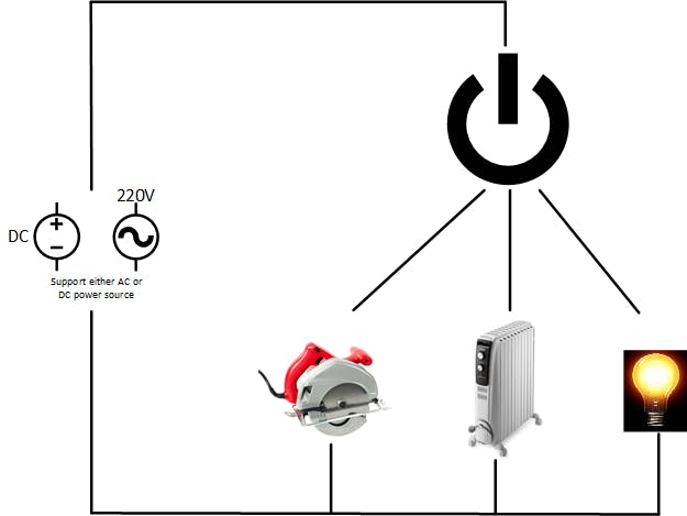
This project is a continuous variator of supplied power for 220V/110V power tools, lights or heating. It works for AC as well as for DC power supply, that is why it is named Universal. Compared to existing built-in speed variator if the power tool has one, our solution using 600V CoolMos C7 makes less EMI and noise. Moreover, it works for controlling AC or DC power supply with the same hardware. It is useful because of you can add new functionaliies to low-end electrical equipment.
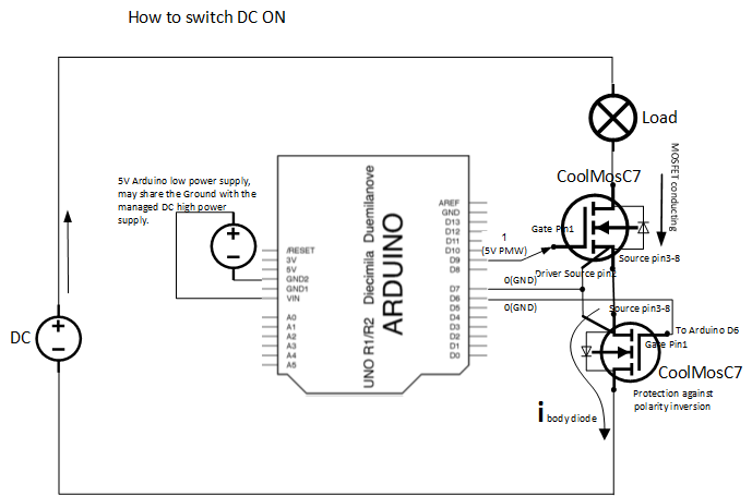
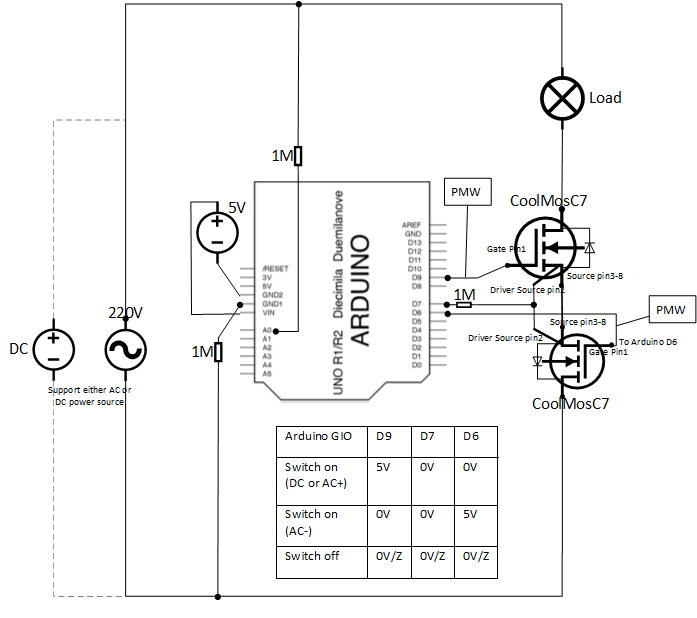
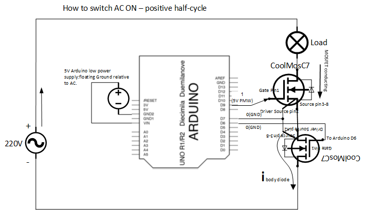
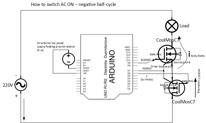
To vary the supplied power, two 600V CoolMos C7 are tied back-to-back, then together are put in series with the load. The pack of two CoolMos C7 controls the supplied power by controlling the supplied current. The pack in turn is controlled by an Arduino which PWM modulates the supply current passing through the two CoolMos C7.
The circuit and components are not galvanic isolated. Using a Wireless shield this power variator can be remotely controlled.
One use case is to vary the speed of low-end power tools such as drills, saws, and which don't have speed variation. Many times, we would need the tool to run at lower speed to avoid damaging the part we are working on, or sometimes just to reduce the noise for neighbors.
Another use case is to fine tune the electrical heater's temperature, and automatically switch it on/off depending on the ambient temperature.
Another use case is to control a fan's speed and stop it as a function of ambient temperature.


Comments