

Hardware components | ||||||
 |
| × | 1 | |||
AS THIS PROJECT USES MAINS VOLTAGE POTENTIAL AND CAN BE LETHAL, PLEASE ONLY ATTEMPT THIS PROJECT IF YOU FULLY UNDERSTAND THE DANGERS AND KNOW WHAT YOU ARE DOING!
For a while now we have been getting brownouts at home. This is where the mains voltage dips to such a low-level, lights will dim or flicker and in the case of mains powered digital clocks or electronic gear they may restart in an unpredictable way.
Normally in our case the clocks will just need resetting and the router throws a wobbler. The electricity board has blamed swans or third-party tree’s! Basically, I wanted a way of recording when the brownouts occur as I’m not always home. In some cases, the electricity was not off long enough for the clock to need resetting although the lights would flicker.
Our CCTV system is very sensitive to power fluctuations.This is where the Arduino comes in. It will record very small interruptions in time even when I’m not home to watch the lights and record the time they happened so as I can go back to the electricity company armed with information.
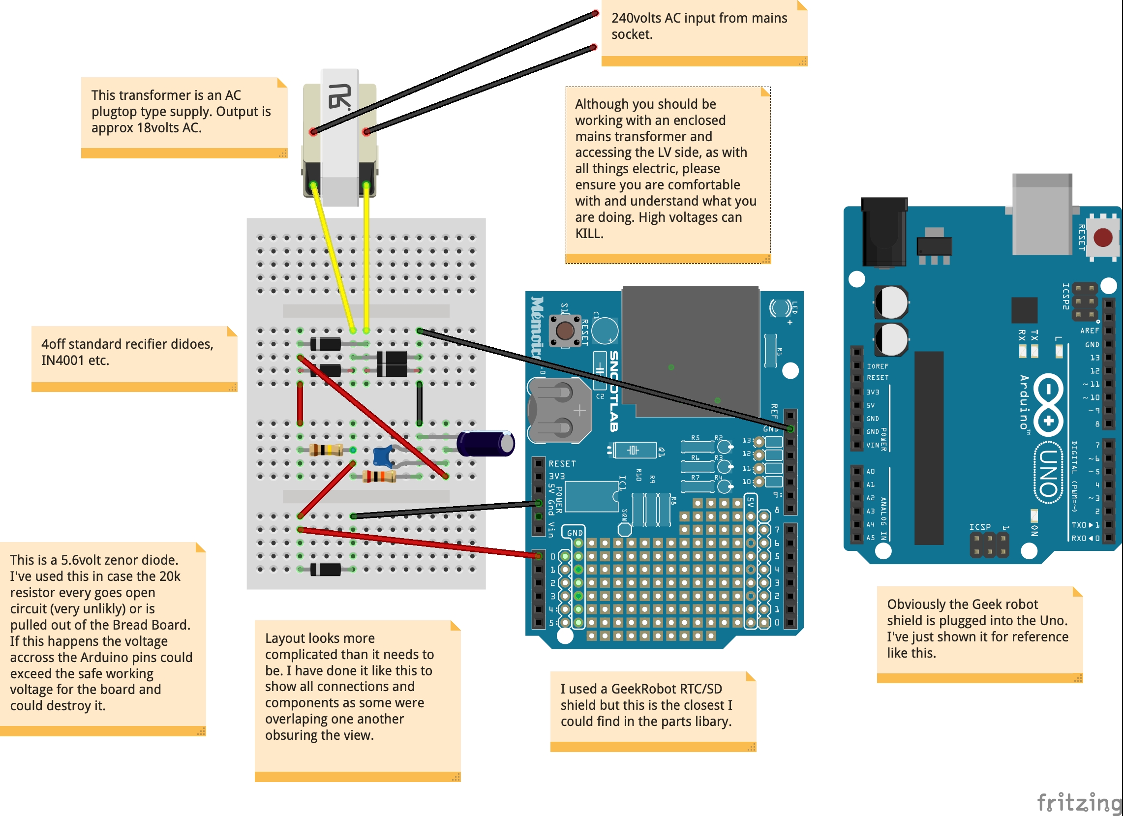
I have used an old plug top PSU, 230v AC in 20v AC out which is ideal as I can rectify the AC and place minimal smoothing on the DC output. Also, as the PSU is fully isolated from the mains supply there is little chance of electrocuting myself. A big tick in the box for that! This way, when we get an interruption it isn’t masked with excessive smoothing on the output which would artificially keep the output stable, at least longer than I would want.In the schematic you can see a standard full wave rectifier setup made of 4 IN4001 diodes (D1, D2, D3, D4) which feed across a potential divider (PD), namely 2 resistors, a 100k (R1) and a 20k (R2). As the ratio of the PD is 5 to 1, I will be measuring about a fifth of the secondary AC winding supply across R2 (about 4volts).I have also placed a 5v6 zenor (D5) across R2 just in case R2 ever gets pulled out of the bread board, this way the voltage on the Arduino pins can never get above 5.6volts. I am then smoothing the output across R2 with a 4.7uf and a 100n capacitor. This output is connected to the Geekrobot (GR) RTC/SD shield that’s mounted to an Uno. Cathode of D5 to pin A0 and Anode to a ground pin of the GR board.There is virtually no loading on the monitored supply due to the high impedance of the GR board so the results shouldn’t be affected too much.
The AC PSU is plugged into a normal mains power socket. The Arduino however is powered from a power bank which is being charged from the mains. So, if the supply to the house is interrupted the Arduino is happy to continue running from the power bank but the Brownout is recorded. Even if we lost power for hours, the battery pack would keep the Arduino going for some time. You will need a power bank that can supply power and be charged at the same time. Please also make sure it stays "awake" when powering the Arduino. You may need to add an additional load to the supply output. All depends on the power bank really.
The sketch contains information on how it works in general. You will need to change values to suit your home mains power input and the output from your mains PSU. As stated, the DC should be smoothed but minimally otherwise it will be more difficult to detect any dips. I’m only monitoring for voltage drops but some small changes/additions in the code would allow you to capture rises. I’m also not too concerned about measuring the exact dip, volts wise, I just want to record the fact it has dipped below a pre-set (unacceptable!) value.
Wikipedia says the UK mains supply should be 230v +10%/-6% so I’ll be looking for a dip below about 216v AC.With the lower value in the sketch set to 580, I should see dips in the power that are below 210volts AC. As stated previously you will have to tweak these values to suit your mains You will need the HCRTC library for the Arduino which I have included on the Google drive.
If you spot any mistakes then please let me know so as I can correct them.The link below will get you to the Sketch, schematic, component list and bread board layout for the project.
https://drive.google.com/drive/folders/1JB2ph-IEE6zXqnaPQNnCBSKcTfrR1L9k?usp=sharing
Also on my youTube channel:


Comments