This component can be essentially any appropriately sized housing that can be mounted.
×
1
Mounting Adhesive
This is just recommended but proper mounting hardware is also suggested. This can also be used to attach the bracket for the servo lever arm
×
1
Zinc Fastener
These were what we used to construct the bracket for the servo arm.
×
1
Adafruit Tiny breadboard
The smaller the breadboard, the better and this quarter size board is perfect for small projects. The one shown in the photos came with the Maker Kit but the Adafruit Tiny board is the optimal choice.
This tool is by no means required but is recommended if a slot in the housing is not already present.
Story
Overview
For the WiFi Connected Lock, we wanted to create a simple, yet reliable method of locking doors without modifying the existing internal lock mechanism. Our strategy was to mount a special bracket to the servo arm which would engage/disengage the lock from any internet connected device. For use on a phone, we recommend using Mobicle.io which allows users to assign buttons to their Particle Photon using their existing Particle account. Mobicle doesn’t require any modifications to the code and is one of the easiest ways of controlling functions for the Photon. The (soon to be linked) video describes the process of using the lock in action.
Video demonstrating the working prototype
Step 1
The first and foremost step towards completing this project is to build the code for your hardware. Our Photon uses the same language as Arduino and there are many good sources of information if needed. The code itself is very simple so there should not be too much to cause trouble. It is recommended to add push buttons which would act as physical buttons from Mobicle, but this requires servo instructions in the loop. https://build.particle.io is the website where you can edit the code for your Photon. The bulk of the lines is for publishing event data which can be monitored on the Particle Console with the data consisting of the servo position.
Code for integer declarations, inputs/outputs, and subscribe function
The loop and string command for the servo
Handler function for publishing event data
Once the coding is complete, it is then time to set up the buttons on Mobicle. This website uses the same login information as your Particle account and does not require you to create another account. Make sure your Photon is on before you sign in or else you won't be able to sign in. Under My Devices, select your photon. Then select Create a Button, where you can select the Servo function and enter 90 or -90 for the function argument. For our prototype, 90 is for the button named Lock and -90 is for Unlocked. Then name your buttons and you should see a similar screen below.
Mobicle page with ideal buttons
Step 2
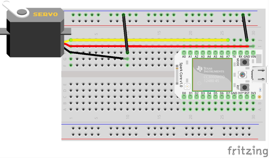
If push buttons are desired, then this is roughly what the breadboard looks like. The button inputs use a pull up resistor so there is no external resistor required. However, the loop statements are not shown on the code above due to some complications with the publish data in the loop. Whichever configuration you choose, the circuit diagram is fairly simple. The push buttons must assigned to any pin on the digital side but preferably not directly next to each other.
Single servo with two push buttons layout
Basic breadboard layout (one used in the video)
Step 3
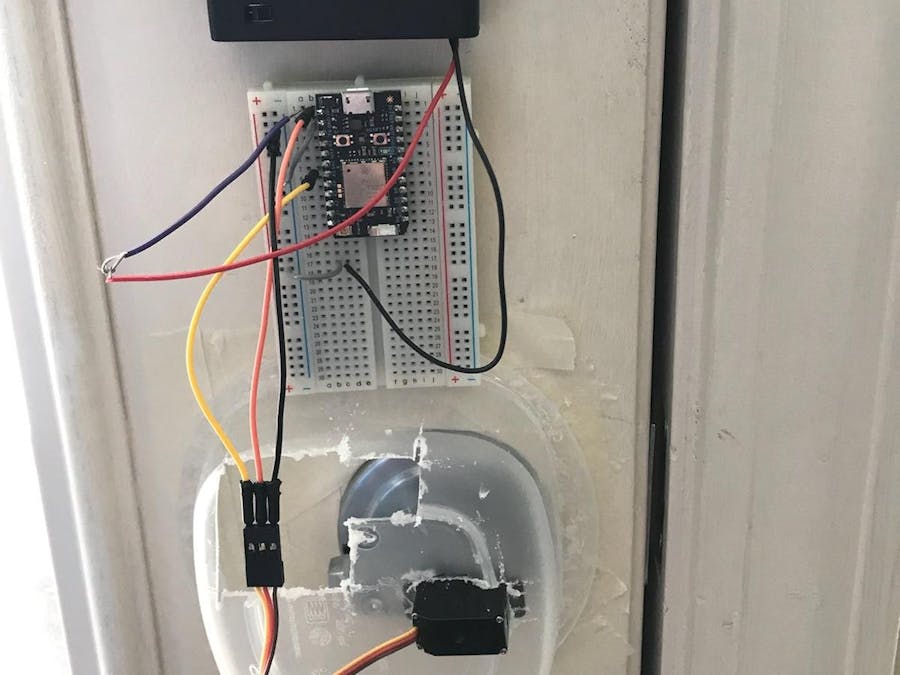
When constructing the housing for the breadboard and servo, it is important to leave plenty of space for the servo arm to fully rotate the lock. Anything blocking or rubbing against the servo could result in harm to the motor. It is also important to note that the door lock must align properly with the slot on the door frame, otherwise there will be trouble fully engaging the lock. The housing material itself does not matter but should be light as possible. Usually, the cheapest and most common household item is Tupperware, but there are dedicated electrical housings such as the one linked in the list of materials. We intended on placing the battery pack inside the housing for aesthetic reasons, but this would greatly increase the size of the housing and make replacing the batteries extremely trivial. We recommend putting the batteries adjacent to the housing for convenience.
Approximate size of housing necessary
Expanded view of the full assembly, notice the benefit of a smaller breadboard such as a Adafruit Tiny
The container was machined so that the servo motor fit tightly in the groove and not allowing any rotation while in motion. An emergency hole was cut in the back in case there was a need to access the bolt lock without removing the housing. In order to attach it to the door the area around the bolt lock was first prepped with masking tape. This allowed for the housing to be directly hot glued to the door, keeping the servo as close to the lock as possible. Then using command strips the battery pack and breadboard were placed above the housing as seen in the photo.
Step 4
For the servo itself, we recommend a much more powerful one than seen in the photos. Our originally chosen servo was found to be defected, so the EMAX ES08A II seen in the pictures and video was just for the working prototype. If this servo can lock a door with only 1.8 kg-cm of torque, then it is sufficient to say that most servos can perform this job. The servo seen on the list of materials makes almost ten times more torque and is a much higher quality item. The servo arm used in the video is two arms and two zinc fasteners glued together with super glue. If a 3-D printer is available, there is a CAD file of a proposed arm attachment that should fit most deadbolt locks. If you want to create your own arm attachment, then mounting hardware will be your cheapest option.
Step 5
It is important to test the servo multiple times on multiple door locks to see if any issues present are in the code or construction of the device. Depending on the orientation of the servo, the function arguments may need to be switched for the Lock and Unlock buttons. If the servo does not finish its' full rotation, then be sure to stop the servo to prevent any permanent damage.
Conclusions
The estimated cost of the entire project from the list of materials is $60-$70 (not including tools for creating housing). This project is a great way for beginners to get a better understanding on how to control servos, publish/subscribe data, and use the Particle Photon. Thank you for visiting our project and let us know what you think!
This a Creo file that can be used if a 3-D printer is available and replaces the zinc fasteners that could be glued on the servo arm. Inner Diameter fits most locks and 8-32 UNC holes are tapped.
Schematics
Circuit Diagram
Any pin will work but this particular example chose A7 for the servo. The battery pack will also be grounded with the servo and the positive wire goes into the Vin Pin. Sourced from http://diotlabs.daraghbyrne.me/6-controlling-outputs/servo/
This code with buttons created on Mobicle will allow users to unlock/lock doors and publish event data. Argument parameters for the buttons: Unlocked = -90 Locked = 90
// Mike Stewart
// Lock Setup & Configuration
// MEGR 3171// Variable & integer declarations
int servoPin= A7;// servo name declaration
Servo EMax;int servoPos=0;int boardLed= D7;// flag used to trigger if we have a new status for the event
bool lockActivated= false;void setup(){// the onboard LED is our output as well as the servo
pinMode(boardLed,OUTPUT);// enables the servo as an output of the functionpinMode( servoPin,OUTPUT);// attaches the servo on the A7 pin to the servo object
EMax.attach( servoPin ); // register our particle to control the servo
Particle.function("servo", servoControl); // keep a cloud variable for the current position
Particle.variable("servoPos" , &servoPos , INT );// The subscribe function allows our photon to receive data from another person's photonParticle.subscribe("Lock Activation", myHandler);}void loop(){// Loop for publishing lock events to the Particle Consoleif (servoPos = -90){ if(lockActivated==true){ Particle.publish("Lock Activation","Locked",60,PRIVATE); digitalWrite(boardLed,HIGH); delay(500); digitalWrite(boardLed,LOW); lockActivated=false; }else{ // Otherwise this status isn't new and nothing should be done}}else{if(lockActivated==false){ Particle.publish("Lock Activation","Unlocked",60,PRIVATE); digitalWrite(boardLed,HIGH); delay(500); digitalWrite(boardLed,LOW);lockActivated=true;}else{}}}// commandfor servo over the cloud
int servoControl(String command){ int newPos= command.toInt(); // Parameters for servo degrees of rotation
servoPos= constrain( newPos, -180 , 180); EMax.write( servoPos );return1;}// the myHandler function is called when the cloud tells us that our friend's event is publishedvoid myHandler(const char *event, const char *data){ if (strcmp(data,"Locked")==0) { // if your friend's Lock is engaged, then the board LED will turn on
digitalWrite(boardLed,HIGH);}elseif(strcmp(data,"Unlocked")==0){ // if the Lock is disengaged, then the board LED will turn off
digitalWrite(boardLed,LOW);}else{ // data shouldn't be anything but the two options listed above
}}


Comments