

Hardware components | ||||||
| × | 1 | ||||
| × | 1 | ||||
 |
| × | 1 | |||
Software apps and online services | ||||||
 |
| |||||
Recently I moved to a new city with a improved public transportation ecosystem less dependent on automobiles. As a result, I have been utilizing a bicycle as part of my daily commute which does occasionally include riding in the dark on some days depending on my schedule. To make myself visible during these conditions, I decided to invest in a set of cheap, rechargeable bike lights off Amazon.
They are definitely not the highest quality in terms of fit and finish but they have so far satisfied their one core requirement of decreasing the likelihood of me getting hit by a Waymo.
However, one design decision of the tail light specifically has frustrated me to no end: the lighting modes.
I don’t know why this was deemed to be a necessary feature but the light have 4 different lighting “modes” that you can cycle through which include high brightness, low brightness, slow blinking, and fast blinking. While this may seem like a nothingburger of a problem, over the course of the last few weeks it has been getting pretty cumbersome to press a button 4 times to turn on my lights.
The PlanYou might be thinking, well why don’t you just look for another light with a simpler ON/OFF switch? Or just design your own light? Or develop a strategic plan to improve your work life balance through various daily affirmations and understand its impact on overall physical and mental wellbeing?
Nah… those options would all be way too simple…I knew what I must do...
Spend hours of my free time reverse engineering a product likely designed with a cost target of less than a snickers bar to fix a problem which is even nit-picky for me... and that's saying something.
My goals for this project are pretty simple:
- Reduce the light to only a single mode, like the blinky one I have been primarily using
- Reuse as much as possible from the original light, including the original housing, battery, and PCB
Initially, I had concerns about the second item. Mainly due to my estimation that this light was likely designed around an ultra cheap, no-name microcontroller or ASIC that would be a pain to get a datasheet for, or piece together to toolchain to reprogram it if it even has that capability (likely one time programmable or even mask ROM).
To avoid this additional time dump, I decided from the start to plan around replacing the MCU with something I was familiar with (I.e. ATtiny, PIC).
Opening this thing upSince these are designed to be "Fearless" in all weather conditions, measures have been taken to weatherproof the housing by sealing together the transparent light bezel and the black back shell in addition to adding a rubber plug for the microUSB charging port.
Yes, this thing unfortunately has a microUSB port in 2026... I’ll give them a break considering this design has likely been in circulation since before USBC or die snobs like myself were being pushed around in a stroller.
To separate the bezel from the back shell, all I needed to do was apply light force with a flathead screwdriver to the edges of the light. I was pretty careful here since I am planning to just reglue these parts back together after I make my “design revisions”.
With a little force and finesse the two halves of the clamshell opened to reveal a pearly white PCB assembly which includes all the onboard electronics.
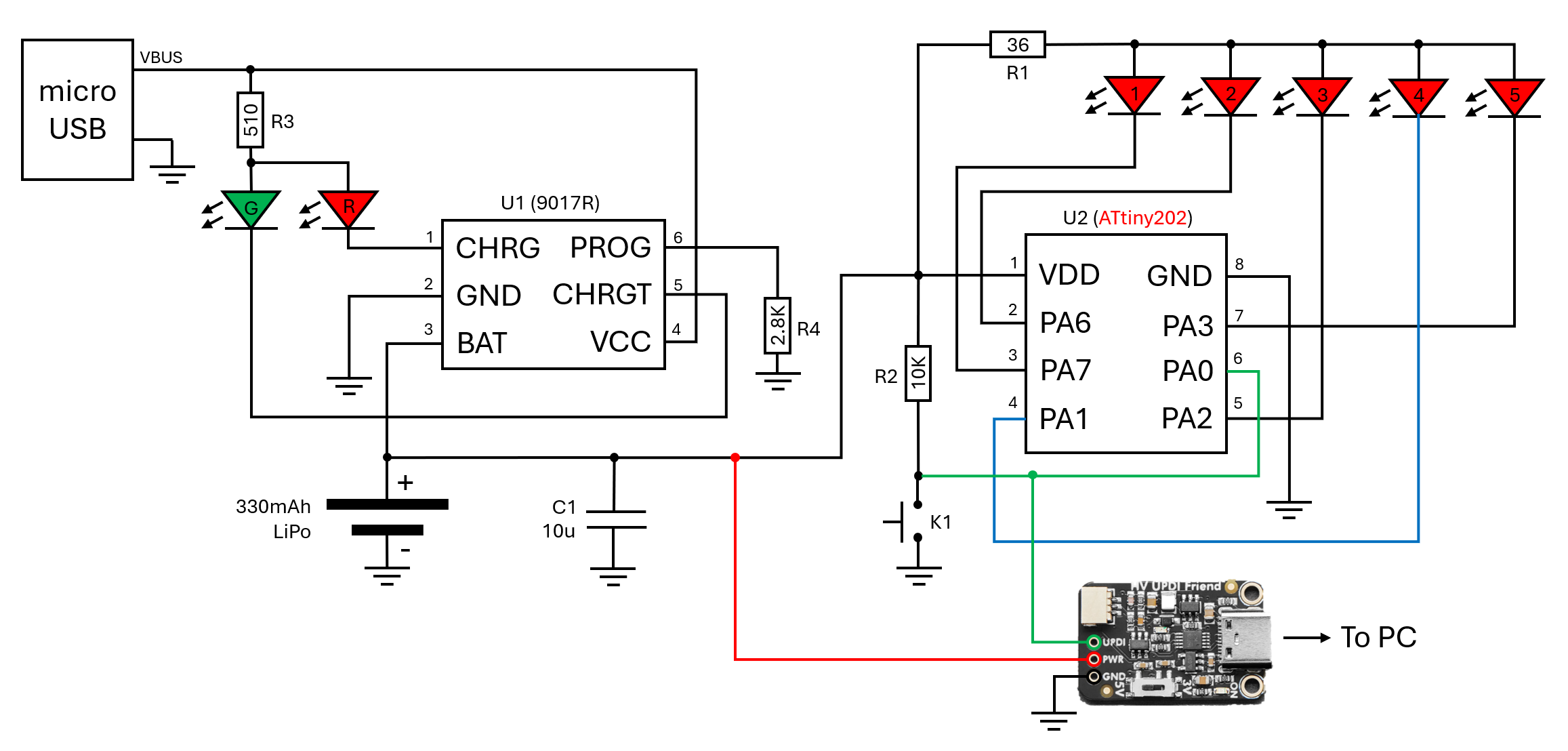
In order to know what I was working with, I decided to first reverse engineer the schematic. Thankfully, with the low cost, and as a result, technical simplicity of this device, this was a relatively trivial process with a DMM and some good eyesight.
To start off, the main power source of the device is a 330mAh Lithium Polymer (LiPo) battery which is soldered directly to the PCB on what I am going to consider as the bottom side. Also on the bottom side is our charging input via a microUSB connector. If you look closely you will notice only pins 1 and 5 of the connector are used as this connector is for power only and the D+/D- lines are unused.
The +5V VBUS supply is connected to a SOT23-6 package which is a linear, single cell, lithium ion / lithium polymer charge controller (FM 9017R). A 2.8k pulldown is connected to it's PROG pin which configures it for 392mA charging. The 9017R has two open collector outputs to control indictor LEDs based on the battery charging status.
The main controller of the light is a classic unknown, likely 8-bit, MCU that has had its information lasered/sanded off its SOIC-8 package; if it ever was there in the first place. Believe it or not, when I originally saw this device through the rose colored light bezel, it was actually a pleasant surprise as I was originally expecting a “glob-top” style package in which the die is directly bonded to the board with a dab of acrylic over the top for protection. With an SOIC-8 footprint on the board, I was hopeful I could find a replacement MCU with a similar pinout for transplant.
Lastly, I discovered a kind of interesting hardware feature of this board you may have noticed in my schematic above: each LED is connected to a dedicated GPIO pin…
This surprised me considering none of the (4) lighting modes utilize this capability to individually illuminate each LED with some sort of animation. My guess is that this was to avoid exceeding the current rating of each individual GPIO output by driving all the LEDs on one pin or the additional BOM cost of adding an separate transistor as a buffer.
Still pretty curious why they didn’t at least add one sequential mode to take advantage of this… I knew I would have to utilize this Easter egg in my updated design!
Selecting a new microcontrollerNow that I had a reverse engineered schematic of the PCB and a pinout for the original MCU, I was ready to figure out a new brain for this thing.
Looking at the original MCU pinout, we need to find a device meeting the below criteria:
- SOIC-8 package
- VIN range within the voltage swing of our LiPO battery
- VCC on pin #1
- GND on pin #2
- Input with interrupt capability on pin #4
- Low side outputs on pin #2, 3, 5, 6, 7
- Ideally supported by an existing Arduino core because am lazy
I started my search by compiling a few options I knew of that came in an SOIC-8 package and might fit the above requirements and created a table with their pinout.
After reviewing all options and comparing additional metrics such as operating voltage range and power consumption, I decided to go with the ATtiny202 series since it's pinout matched the original device pretty closely, allows UPDI programming with (1) pin that could also act as our switch input, and has an Arduino compatible core via the megaTinyCore.
Replacing the MCU and modifying the PCBAfter I received the new MCU from Digikey, it was time to conduct the transplant. I used my handy dandy hot air rework station to desolder Mr. No Name and then soldered in our new ATtiny chip.
HV UPDI Fun and PCB Rework
One thing you may have noticed in the pinout table is that I am need to use pin #6 (PA0) for programming the ATtiny202 via it's UPDI interface. I plan to also reconfigure this pin as GPIO for our mode switch input after boot.
Since we don't have a dedicated RESET pin to grab hold of the ATtiny before the pin is reconfigured, we will need to take advantage of the high voltage UPDI programming feature of newer ATtiny MCUs. This will allow us to enter reprogramming via applying a 12V pulse from our reprogramming tool (Adafruit High Voltage UPDI Friend) without losing any GPIO!
However, there are a few important things to consider when using a HV UPDI pin for GPIO:
- Circuitry connected to the UPDI pin needs to be tolerant to a 0.1 - 1ms 12V pulse
- When configuring the pin as an output, programming must only be initiated after a power toggle, within the 10ms hold-off time implemented for UPDI pins
Since this was my first project using HV UPDI and I wanted it to be pretty foolproof and also allow for reprogramming with the battery soldered in, I decided to just make some modifications to the PCB to instead use pin #6 for our switch input and rewire pin #4 to LED #4.
After getting everything soldered in, I connected up the programmer, got everything powered and tried uploading blink to make sure I didn’t manage to goof something along the line. Thankfully my test was successful and the the board blinked to life!
As mentioned previously, I wanted to take advantage of having each LED connected to a dedicated GPIO pin by adding some sort of sequential output. I ended up deciding on a sequential inward fade with a 250ms delay between stages.
Since I wanted to reduce the sleep current consumption as much as possible, I put the MCU in power down mode when the output is turned off. This substantially reduces the quiescent current consumption as we will measure later.
Lastly, since the onboard tactile switch has a slight contact bounce, I added in some timer logic to avoid retriggering the interrupt again within 50ms of an activation.
Extra Credit: Power consumption measurementsOne other factor I thought might be interesting to compare before and after the upgrade is the power consumption of the device during sleep and each of its lighting modes.
To do this, I utilized my handy Nordic Semiconductor PPK2 to replace the original LiPO and measure the device current before replacing the original MCU and after the “upgrade” to the ATtiny.
Based on my measurements, I was able to decrease the device sleep/quiescent current by 85.7%! This is actually a pretty nice “icing on the cake” situation as this light will likely spend most of its life sleeping (must be nice...).
The average current for my new, sequential mode is a bit higher than the previous 200ms blink mode I was using but I'm willing to sacrifice the extra battery juice for the cool factor.
ConclusionThis project was a fun, simple project to get me back into the mood of tearing down and reverse engineering/upgrading consumer electronics. If you have recommendations for what devices I should work on next, please leave a comment below and also check out my other articles here on Hackster.io!
P.S. I actually saved the original microcontroller and have been thinking about soldering it into an SOIC-8 breakout and trying it with a few different programmers to see anything will detect it and read out the flash... I think it's a long shot but might be a fun study!


Comments