
Hardware components | ||||||
| × | 1 | ||||
 |
| × | 1 | |||
_ztBMuBhMHo.jpg?auto=compress%2Cformat&w=48&h=48&fit=fill&bg=ffffff) |
| × | 1 | |||
Hand tools and fabrication machines | ||||||
 |
| |||||
In my pursuit to build a clock for every possible area of my apartment, I decided to purchase (4) SparkFun 6.5" 7-Segment Display modules and their Large Digit Driver boards which allows for easy control of the display segments over a Serial Peripheral Interface (SPI). Similar to many of the projects currently on my backlog, I purchased these parts around a year ago and am just now getting around to cobbling them together into something.
Problem StatementAfter wiring a display up to an Arduino UNO and writing a basic test program to run through each of the segments, I realized one very important flaw of the SparkFun displays: the aesthetics.
While the design/layout of the large led modules used in the display do evoke the rough image of it's much smaller counterpart, the lack of that distinct black/grey face and white housing really take away from the fantasy of owning a supersized LED segment display. It was at this point I knew what I must do: spend 3x the effort I allocated for this project to fix something only I would be frustrated with.
Time to get modeling...In order to have a good basis to design my case around, I first needed to locate a model of the display itself. Unfortunately, I searched everywhere and could only locate a kinda rough model that wasn't dimensionally correct enough to design what I needed. Ugh here we go...
Based on that disappointment, I then spent time meticulously measuring and modeling the display as accurately as possible. This took multiple attempts due to the odd shape and positioning of the display segments. Thankfully I was able to use my 3D printer to test print the shape multiple times to compare to the actual part and adjust the model. Hopefully someone else will get use out of this for another project so I don't feel like I completely wasted hours of my life...
After perfecting my display model, I could then finally start the project by modeling the 7-Segment housing. I was originally considering modeling the case in (2) pieces: a face (black) and a back shell (white). However, I eventually gave up on this based on the idea that it would be better to model it in one piece that could either be printed in white and painted or printed in multi-color if you're bougie like me... #BambuA1
For attachment, the display module has (3) 2mm radius holes which I attached to the case using #4 self threading plastic screws. See BOM at end for McMaster part numbers!
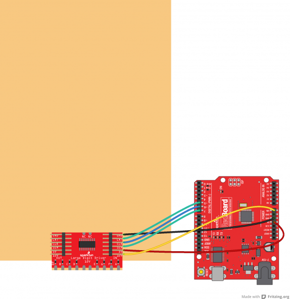
Controller BracketsNow that I had the display model sorted out, I needed to figure out some way to attach a controller for driving the SPI interface to the displays. The displays themselves are just LED modules that can be easily controlled by an add on driver (SparkFun Large Digit Driver) that is soldered to exposed pads on it's backside. The driver board is just a TPIC6C596 which is a 8-bit shift register that has higher current open drain outputs compared to other more common shift registers such as the 74HC595.
One note: the TPIC6C596 is a 5V logic device so it will need to be controlled by a device operating within at least 0.85*5V = 4.25V according to it's datasheet. This means that you will need to use a level shifter to control the displays using a 3.3V logic device! Man, I really wish SparkFun would just use the TPIC6C596's newer, 3.3V compatible sibling, the TLC6C598...
Since the goal for this project was to use as much existing Hardware as possible, I decided to utilize an Arduino Nano ESP32 with the Nano Screw Terminal Adapter for easy connection to our necessary 12V input supply for the display segments. The bracket is a pretty straightforward design that attaches via the same (3) 2mm radius holes in the display. After putting together the Nano design, I decided it might be a good idea to also quickly throw together a similar bracket to attach an UNO. Be sure to check the above image to confirm which files you need!
Printing Time!After all the design work was complete, I then got to printing each of the display housings and the brackets. As I mentioned earlier, my end goal for this project is to make a clock so I printed (4) of the housings in multi-color and (1) of the controller brackets. Just a note, I was planning to use a power adapter with a barrel jack output for my 12V input supply so I added an attachment point in the Nano Screw Terminal bracket to install a female barrel jack.
Assembly and TestingAfter all the modules were printed, I then started assembling everything which was pretty straightforward. As mentioned before, the display modules attach to the housings via (3) screws. The "controller" display module gets an extra bracket to mount the controller which goes on the back of the display. The main power input (12V) feeds the display segments and the VIN of the Nano/UNO and programming can be accomplished via the USB port even after the controller is installed.
The display to display wiring is pretty straightforward also. I just used a bunch of Dupont cables to daisy chain them all together as guided in the SparkFun hookup guide.
One key reminder is that if your are using a 3.3V logic board (i.e. Nano ESP32, Nano RP2040, etc..), you will NEED TO ADD A LEVEL SHIFTER AND 5V POWER SUPPLY. The 3.3V Nano boards unfortunately only include a 3.3V switching converter so the 5V (VBUS) terminal is only powered when a USB cable is connected. Keep this in mind when you are planning your project as it can be a pain to piece this together on the screw terminal adapter!
Closing Thoughts / Future ImprovementsNow that I have my hardware sorted, my next steps will be to put together a basic program to read the local time via NTP and format it onto the displays. Looking back on this project, I really should have just used an Arduino UNO R4 WiFi probably rather than going through the trouble of adding a 5V power supply and level shifter to the Nano ESP32. I went down this path to try and utilize HW I had on hand but I would recommend others to go down the UNO path if possible!
BOM (Screws):- #2 x 1/4": McMaster 92295A111
- #4 x 1/4": McMaster 92295A100
- #4 x 3/8": McMaster 92295A101


_3u05Tpwasz.png?auto=compress%2Cformat&w=40&h=40&fit=fillmax&bg=fff&dpr=2)
Comments