One day when I tidied up my cellar, I found a Z80 chip from an old computer. In the '80s and '90s, this processor was very popular, and I dare to say the most popular processor ever. So I got the idea to breathe new life into it.
The Z80 has a tinker-friendly 40-pin DIP housing, but unlike modern tinker-friendly Processors like the ATmegas, there is no built-in RAM, program flash or any peripherals. It has only the raw core functionality of every Processor, which is to make basic calculations on some bits and bytes.
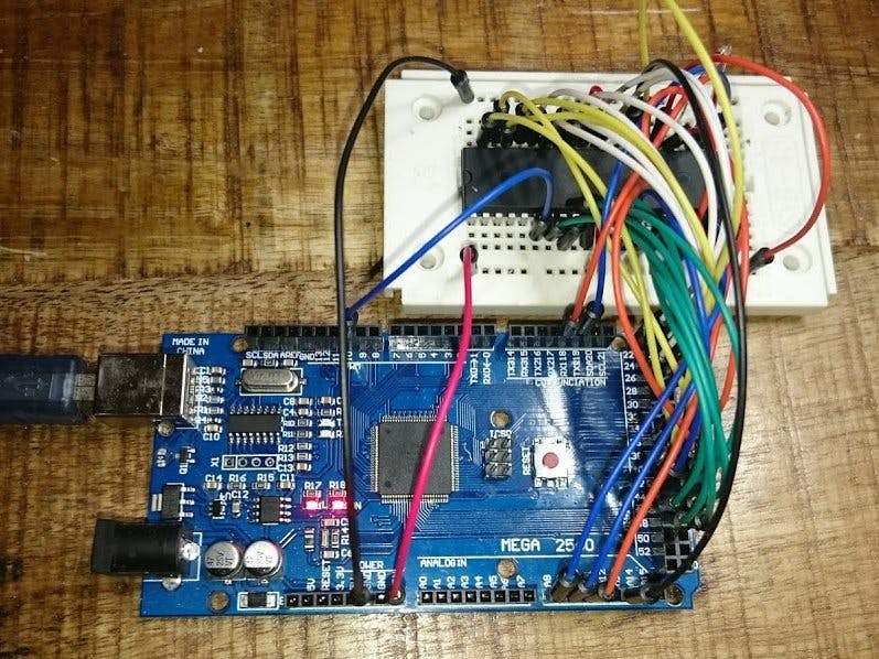
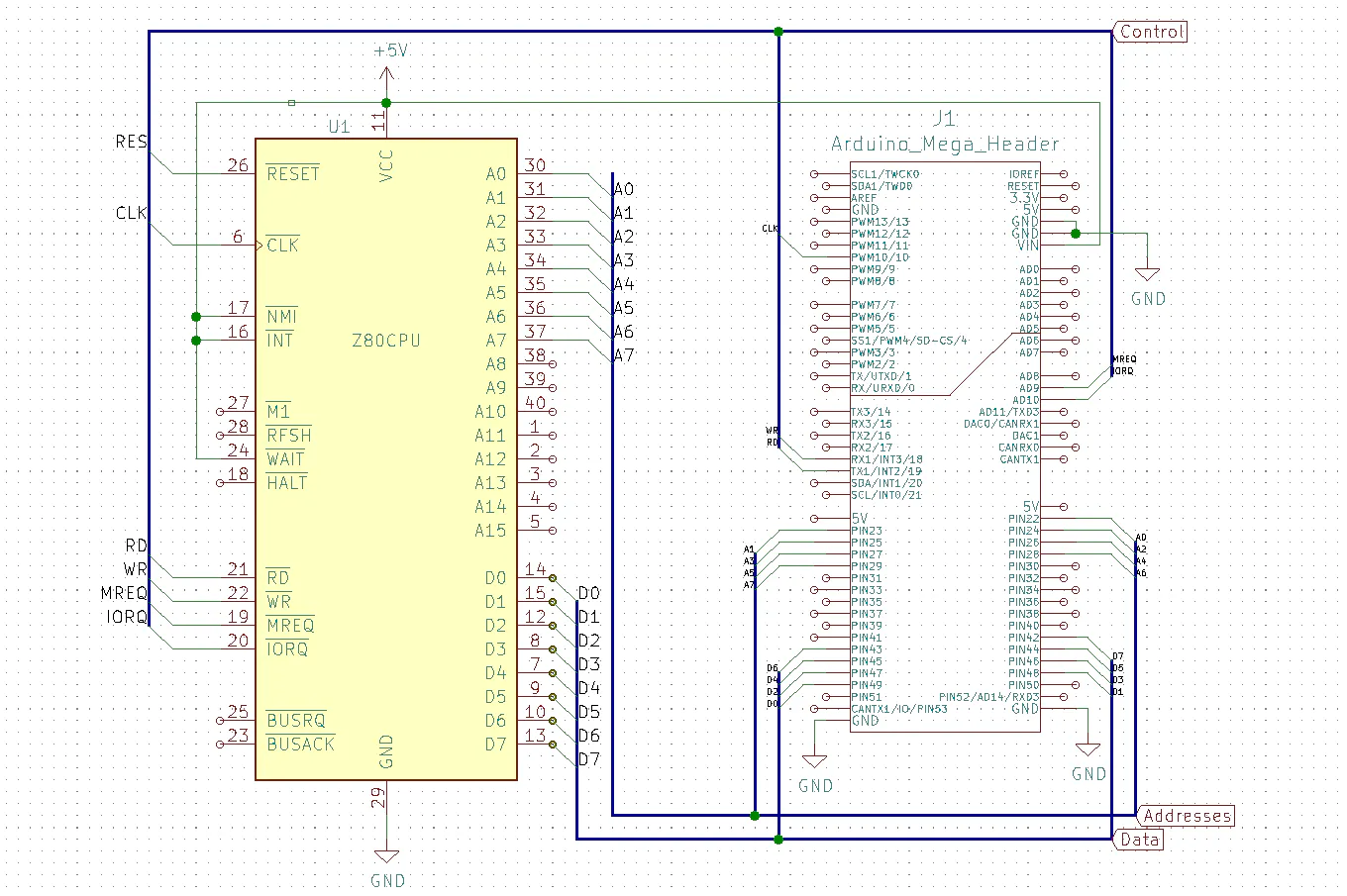
With a bunch of jumper wires, a small breadboard and an Arduino Mega that emulates ROM, RAM and serial IO, I made a fully fledged Z80-based computer!
This is just an academical fun project without any practical relevance, but it teaches you how microprocessors still work in detail!
Watch the video, if you are interested in the details!


Comments