

Hardware components | ||||||
 |
| × | 3 | |||
 |
| × | 5 | |||
| × | 1 | ||||
 |
| × | 10 | |||
 |
| × | 1 | |||
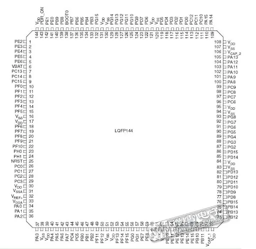
RT-Spark, is an all around embedded board powered by the STM32F407ZGT6 microcontroller and designed to function smoothly when working. The embedded hardware features a number of hardware interfaces such as the LCD, LEDs, switches and etc.
After confirming that the switches and LEDs had been properly connected to the microcontroller, current was flowing into the system for it to undergo testing. After pressing the directional switch, there was a speedy response; a red signal was activated in the workspace, while the screen flashed "Button Up is Pressed."
Breadboard SetupPhase 1: Hardware Wiring
Before writing any code, you need to connect your external components to the correct GPIO pins on the STM32F407ZGT6. Make sure positive rail is connected to 5V and negative rail to GND.
1. The 5 Momentary Switches (Navigation)The code expects these to be Active-Low (meaning they connect to Ground when pressed). The internal pull-up resistors will be enabled in the software.
- Up Button: Connect to pin PG0
- Down Button: Connect to pin PG1
- Center Button: Connect to pin PG2
- Left Button: Connect to pin PG5
- Right Button: Connect to pin PG6
These are also configured as Active-Low (they turn ON when the pin outputs 0V). Connect a 220Ω resistor in series with each LED.
Anode (Longer Leg):
- Red LED: Connect to pin PA2
- Green LED: Connect to pin PA3
- Blue LED: Connect to pin PA0
Cathode (Shorter Leg):
- Connect each LED to the negative rail of breadboard.
STM32CubeMX SetupPhase 2: STM32CubeMX Project Setup
Open your STM32CubeMX application and start a new project with the STM32F407ZGT6 microcontroller.
Step 1: Configure the LCD Backlight1.- Find or search
PF9in the bottom-right search box. - Left-click the flashing pin and select
GPIO_Output. - Right-click the pin, select "Enter User Label" and type
LCD_BL.
- Find or search PD3 in the bottom-right search box.
- Left- click the flashing pin and select
GPIO_Output. - Right-click the pin, select "Enter User Label" and type
LCD_RST.
1. Look at the left-hand sidebar in STM32CubeMX. Find the "Connectivity" category and click the little arrow to expand it.
2. Click on FSMC. The middle of your screen will change to show the FSMC Mode settings.
3. Under the "Mode" list, look for NOR Flash/PSRAM/SRAM/ROM/LCD 3 and click the > arrow next to it to expand it. (We choose '3' because your schematic uses NE3).
4. Inside that expanded menu, change the dropdowns to match this exactly:
- Memory type: Select LCD Interface
- LCD Register: Select
A18 - Data: Select
16 bits
1. Go to the Project Manager tab at the top.
2. Give your project a name.
3. Make sure Toolchain / IDE is set to STM32CubeIDE
.4. Click that big blue GENERATE CODE button in the top right corner.
Downloading and Adding the LCD LibraryPhase 3: Downloading the Link
Link: https://sendgb.com/M8kq5c23FwC
Step 1: Download the FileThis will save a file named Header & Source Files for Built-in LCD.zip to your computer.
Step 2: Extract the ZIP File1. Open the File Explorer and locate the file you downloaded2. Right click the file and select "Extract All"3. Open the newly extracted folder.
Step 3: Find the drv_lcd Files
Inside that extracted folder, you should see two sub-folders
- A folder for Header Files (.h)
- A folder for Source Files (.c)
Open them up to find the specific files you need:
- Inside the Header folder, locate
drv_lcd.h - Inside the Source folder, locate
drv_lcd.c
1. Open STM32CubeIDE so your Project Explorer is visible.
2. Drag drv_lcd.h from your computer folder and drop it onto the Core/Inc folder in STM32CubeIDE. Select Copy files when prompted.
3. Drag drv_lcd.c from your computer folder and drop it onto the Core/Src folder in STM32CubeIDE. Select Copy files when prompted.


Comments