

Hardware components | ||||||
 |
| × | 1 | |||
 |
| × | 4 | |||
| × | 4 | ||||
 |
| × | 1 | |||
 |
| × | 3 | |||
 |
| × | 1 | |||
| × | 1 | ||||
| × | 1 | ||||
Hand tools and fabrication machines | ||||||
 |
| |||||
I have always enjoyed making gifts for others, as I feel like it gives me the ability to add more of a personal touch (along with usually being cheaper). I have crocheted and 3D printed projects before, but this time I want to try and tackle a project that involves some coding along with a hardware component. My mom has a lot of jewelry, and so I was thinking of creating a jewelry box for her birthday with a cottage core mushroom forest vibe. There would be one central mushroom that functions as the rotational mechanism for which the majority of the jewelry is hung, along with some lights controlled by a button and potentiometer to dim and switch illumination modes.
InspirationThe first thing I did was begin to sketch out how I might like the jewelry box to look like as my final product. I took to Pinterest to get some inspiration on how I wanted to make some of the components look like, such as the mushroom and jewelry box pictured below.
I first began with a some conceptional sketches with features that were later cut, such as having the mushroom have doors that could swing open to hold necklaces. Ultimately I settled on a design that featured a centralized mushroom that would function as my rotating element that would hold most jewelry, and some complementary ring boxes that would be shaped like blooming flowers if I had the time to implement them.
After I had an idea for what I wanted the design to be, I began to dive into a more detailed plan on what functions my project would have, along with how I would go about achieving these functions. I broke down my project into 2 major components:
- The motorized stepper motor that will control the mushroom for jewelry selection
- The light system that would be control by a button and potentiometer to adjust brightness and lighting patterns
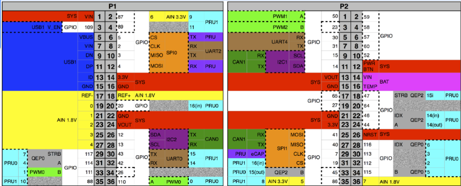
Once I had these two components planned out, I began to create both the pin out and system block diagram for my project, so that I can begin to have a better understanding of the power and inputs needed for my project.
Building the CircuitTo begin the circuit, I started by wiring up the buttons that would be controlling the stepper motor on my circuit. I know that I need 3 functions, and so I wired up 3 buttons with the functions needed: turn left, turn right, and a random position button. The left and right turn will be coded to preform 1 turn to either direction, and the random button will pick random position in the mushroom to present you a random piece of jewelry to wear for the day. The buttons are hooked up to 3.3V power supply, and are using a 1k ohm pull down resistor between the gpio pin and the power supply.
Next I began to set up the controls for the lights, as once again I know that I want to be able to dim the lights on my set up, along with change the mode in which the lights are powered. The button being used to change the mode of the lights uses a 1k ohm pull down resistor connected to the 3.3V power supply. The potentiometer is connected to a 1.8V power supply, and the resistance value is read out to the pocket beagle through a gpio pin.
Overall, the controller section of my design is pictured below, and captures all user inputs that the user can preform.
Finally, when testing the design out, because I did not have access to the light strips during the final design, I started out with 3 simple LEDs which should have let me test the functionality of the lighting modes I wanted to implement. I also used a simple servo to test my code while waiting for my stepper motor to arrive for the final design.
After I finished building the hardware components of my build, I began to work on developing the code for my software. I will go over my code on a very high level, for a more detailed understanding of it, feel free to visit my GitHub repository and browse the project_01 file. Pictured below are some of the flow diagrams for the various coding routines I wanted to implement in my project. The main components of the coding revolve around controlling the servo and the light system, and making sure the buttons are doing what they needed to do. Each of the buttons are programmed to have their callback on press functions to preform their predetermined task, since each buttons was mapped to only one function. For example, the L_Button was programmed to turn the servo counter clockwise.
Further Implementation:
I was unable to acquire certain parts during the semester to fully implement that design that I sought out to create. Because of the lack of final materials, I would hope to have my future design incorporate a string of fairy lights that I had originally envisioned, instead of the three LEDs I used as my stand in. This will probably have future implications on the state of the code as well, as there will probably need to have the lights section reworked to be able to control the entire string of lights instead of 3 individual LEDs. Other than that, I was unable to get to implement the actual 3D printed components because I was unable to get time to 3D print the attached design. However, for future reference, the files created have been attached in this page, however they have yet to be implemented as stated, and so there are possible scaling and attachment issues that have yet to be fixed. This is also true for the stepper motor that is included in the bill of materials, as I instead did most of the coding with the basic servo that is pictured. The coding impact should be minimal, as I should only have to change the size of the steps that the motor is taking, and make sure that I have recalculated the step size to make sure it lines up with the physical mushroom design.
New Additions:
Within the original design I had for the jewelry box, I wanted to add in a mechanical iris ring box, that would unfold into a flower and present the ring inside. The 3D files are attached below, and so if I had more time, I would like to add in this ring box so that there is more variety and another interesting focal point for the project. Along with adding in the ring box of course comes with creating an actual enclosure for both the wiring, and the jewelry itself. Although I had designs prepared for what the final box might look like, I had so much trouble with implementation of the code that I was unable to get that far into the physical specifications of the project.


Comments