

Hardware components | ||||||
| × | 1 | ||||
 |
| × | 1 | |||
 |
| × | 8 | |||
 |
| × | 1 | |||
 |
| × | 1 | |||
Software apps and online services | ||||||
 |
| |||||
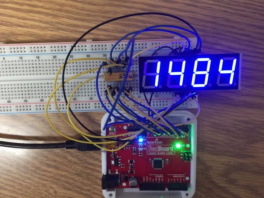
If you have ever wondered how these displays work or wanted to use one in a project, this guide covers the fundamentals. The project consists of a breadboard exercise that explores the basic concepts as clearly as possible without relying on optimizations that might obfuscate how the display actually works.
Sparkfun offers two families of 4 digit, 7 segment LED displays in several colors that sell for under 3 US$ each; one having 10 mm (0.39") high digits with decimal points, a colon, an apostrophe and 16 pins while the 20mm (0.79") tall display featured in this tutorial only has decimal points and 12 pins.
DisadvantagesThe obvious downside to using these relatively inexpensive 4 digit, 7 segment displays is that for full functionality, each pin must be connected to a controlling I/O pin. If you are using an Arduino Uno compatible micro-controller, one of these four digit displays will use from 12 to 16 of your 20 or so available I/O pins.
Starting at roughly 10 US$ more, Sparkfun sells a line of 4 digit, 7 segment displays with some additional circuitry that only requires one to three I/O pins to control one or more 4 digit displays. The extra cost is offset by the convenience of not having to use almost all of your micro-controller I/O pins to drive a single 4 digit display and from having to manage every LED segment in the display. The pricier displays abstract the low level details behind one or more libraries that you include in your sketch. Depending on the project, the more expensive displays may present an overall better value proposition.
Of course, the inexpensive displays can also be managed with fewer I/O pins by using some additional components costing less than 10 US$, but that will be the subject of future tutorials. Lets get to the fundamentals.
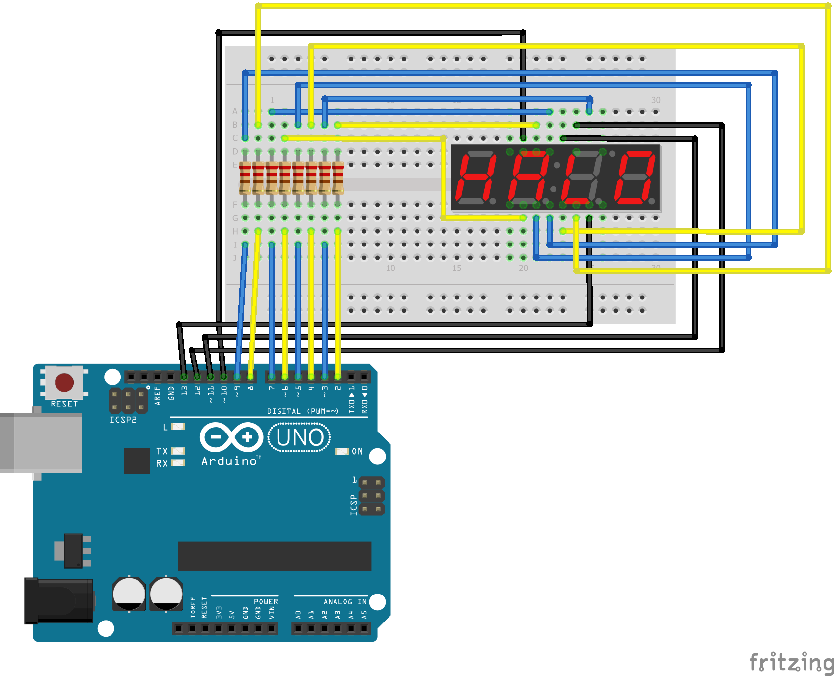
The ATA8401AB display has 12 pins, six near the bottom and six on top. The pins are indicated in blue on the above diagram and numbered counter-clockwise, starting with pin 1 on the lower left. Each digit consists of 7 segments, labeled A-G in green with a decimal point connected to pin 3. Because the ATA8401 is a common anode display, to light any combination of segments on any digit, the desired combination of segment I/O pins must be set HIGH, then the corresponding digit select pin, labeled D1-D4, is set LOW. If two or more digit select pins (shown in orange above) are LOW at the same time, they will display identically, which is usually not desired.
The same segment on every digit shares an I/O pin. The idea is to only light one digit at a time by setting the appropriate segment pins HIGH then bringing that digit's select pin LOW and then quickly turning the digit off by setting its select pin HIGH again after a few milliseconds before going on to the next digit. This happens so fast that our persistence of vision tricks us into believing all the digits are lit continuously and flicker free. In fact, this four digit refresh can happen faster than the shutter speed of most cameras.
Because the segments are only lit briefly, many makers do not use current limiting resistors that can help prevent the LEDs from failing prematurely. However, I like to be a little more conservative and protect each LED segment, including the decimal point with a resistor in the range of 220 to 330 ohms, depending on whats close at hand.
Wiring the project according to the Fritzing schematic:


_3u05Tpwasz.png?auto=compress%2Cformat&w=40&h=40&fit=fillmax&bg=fff&dpr=2)
Comments