

Hardware components | ||||||
 |
| × | 1 | |||
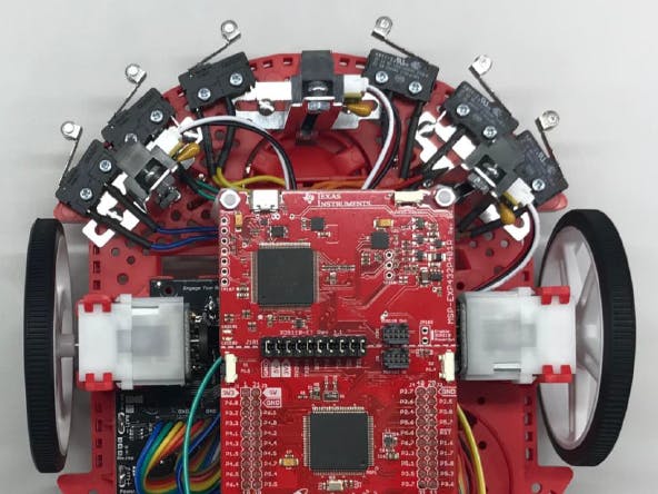
This tutorial shows off a modified assembly guide for the TI-RSLK Maze Edition (www.ti.com/rslk) which uses the RSLK Basic Kit
+ Romi Encoders https://www.pololu.com/product/3542
+ these crimp connectors https://www.digikey.com/product-detail/en/te-connectivity-amp-connectors/63705-1/A111537CT-ND/4142923
The encoders provide an additional sensor capability and also make it easier and cleaner to attach the motors. The crimp connectors help with speeding up the assembly time when attaching the bump switches. An additional tool not mentioned in the guide that will be handy for the build will be a roll of electrical tape so we can tape down headers to prepare them for soldering.
You can find the modified assembly guide PDF for download below as well as a variety of other useful resources, advice, and training links.
The original assembly guides are posted on the TI RSLK website (Basic, Advanced).
Tools you will need: Soldering Iron, Screwdriver, wire cutters and strippers, precision knife, pliers, electrical tape.
How to Solder:https://github.com/maholli/lab64/tree/master/soldering
Check out the tips and tricks video here:Full assembly video here:Coming soon!
Efficient Assembly Guide Tips
Navigate step by step through the instructions to build the kit as efficiently as possible. If working in teams, divide the prep tasks. You may find it very helpful to have the assembly guide pulled up on your phone or tablet so you can look at the diagrams closely while building.
This kit requires quite a bit of soldering. Be prepared.
If you want to practice your soldering, start with the LaunchPad headers first, then do the motor encoders, then the line sensor. The Motor Board has most of the solder points and will take the longest to complete. Screwing down the bump switches also takes some time. You can screw those down and then solder them up to the wiring after they are attached to the chassis (or use the crimp connectors if that is an option for you).
Assembly Duration: 3.5 - 4.5 hours
==Stage 1==
Open ALL packaging,prepare/separate the wires and headers as outlined on the first pages. You can use your hands to break the pins if you have to but it is best to use your wire strippers/cutters to do it more accurately. Normal scissors can work sometimes but you may find they are less than ideal.
Mechanical: Separate and organize your headers from the included straight angle 1x20 and 1x25 pin headers
*note: the 1x20 header is in its own bag but the 1x25 header is located in the line sensor packaging (pink)
*note: if you mess up the count on your pins, it is not the end of the world, but do you best follow the carpenter adage "measure twice, cut once"
*note: the two 1x6 headers for the motor board where you connect the motor are the female connectors, not the male ones you make from the larger connectors
Mechanical: Separate your 6 M/M wires and 6 F/F Wires. If you want to match the colors from the guide, that may be helpful later on. You can prep these wire by snipping off the ends and then wire stripping them to expose the copper strands.
*note: if you don't make a clean cut or clean strip you can cut the wire a bit shorter and start over, easy fix.
Mechanical: Prep the wires for the power and line sensor
*note: Make the short red/blackwires longer than the 1.5” recommended.
KEEP ALL YOUR PARTS ORGANIZED! You will be grateful by not losing any parts when you get to a step. Avoid dropping bits on the floor, do you best to keep them on the work surface, and keep them in view for when you need them.
==Stage 2==
Soldering: take the 2x20 header and snip off one row, then position the 2x19 header onto the MSP432 LaunchPad, pins facing upwards (not downwards!)
Mechanical: If you have IR Sensors (if not, no problem, you can skip this step), take the brackets and screws out of the packaging. On the chassis, you can install the brackets (make sure the angle is facing the right direction, line up the holes correctly)
Mechanical: You can put the tires on the wheels as an easy early step.
==Stage 3==
Soldering: If you have encoders, solder the 1x6 right angle encoder headers to the encoders (make sure to double check which way they are facing in the guide! can't really be fixed after you have soldered them on) then position it on the motor and solder the encoders to the motor tabs (they slip in to sit flush with motor, fold the tabs over the encoder and then solder)
If you don't have encoders, no problem, simply solder wires onto the two copper tabs of the motor (*delicate tabs, be careful!)
Mechanical: at this point you can attach the Bump Switches to the chassis using the small screws and nuts. Follow the guide to align them to the correct holes and it is easier to attach them by feeding the screws from the bottom instead of from the top.
*note: this is a controversial step as some people find it easier to solder the wiring while the bump switch is unattached. If you are using the crimp connectors go ahead and screw them down, if you are soldering the wires, then you can choose if you can solder with them screwed down or not.
==Stage 4==
Soldering: 1x11 right angle header (double check which way it is facing! away and opposite side of black sensors) and 2-pad spacer on the Line Following Sensor (3.3V bypass)
Cut: carefully make a deep incision on the 3 traces on the Motor Board as described in the guide. All you want to do is sever that tiny connection line between the two pads, try not to over cut, just keep it to that small area. You don't need to scratch out the pads or do anything beyond just a simple cut.
*note: it will be obvious later if these cuts are not complete as your robot will exhibit strange behavior when tested. You can use a multimeter to test the continuity between the pads, if they are still connected (closed instead of open) you need to go back over your cut.
==Stage 5==
If you have not already in the beginning, separate and organize your headers from the 1x20 and 1x25 pin headers. You also need to get the 2x female 1x6 female headers from the encoder packaging or the motor board packaging.
*note: This is a harder solder job for the Motor Board so if you have helping hands tool to secure the PCB that works best, or you can work with a partner but be extremely careful to avoid burning fingers. Don't touch a pin or be near a pin that is being soldered, the heat passes right through the metal.
Mechanical: This step is optional but works very well! You can place your headers on the motor board as shown on the diagram and then tape them down with electrical tape so they stay in place while soldering. This is very helpful as a time saver instead of fumbling around with placing each header and then trying to awkwardly solder it. When soldering step is completed, remove the tape and the header will be in the right place.
*note: sometimes when taping components they can be at a crooked angle. If you want them straight just double check before getting started, only solder one pin down, and if it is straight, continue with the rest, or if it is not you can easily correct the position by reheating the joint.
Soldering: Start with the two 1x6 short smaller female socket headers. Solder the various male headers onto the Motor Board (make sure everything is facing upward, the back of the board should be flat!) by following the guide.
==Stage 6==
The bump switches can be attached the chassis as an early step while other soldering is happening. It is much easier to insert the screws from the underside, not from the topside. Then you fasten it with the tiny nuts
Solder or Crimp : The Bump Switches need to be attached to the wiring (pair of 6 wires that were cut and stripped). If you have the special connector (not included in the kit) you can crimp the connector to the wiring and then plug on the wiring to the switch to save time and have a more reliable connection. If you don't have the connector, you can solder the wiring directly to the switch. You can thread the exposed copper side of the wire through the holes in the connector and wrap it around to create a better soldering spot
*note: use of a right size crimp tool is the easiest way to do the wire crimps but if one is not available you can use pliers or the flat end of another type of hand tool to bend the connector wings down and secure it to the wire. It may take a couple of tries but should be possible to make a usable crimp.
Mechanical: Heat shrink is optional, if you don't want to do it or don't know how to do it, that step can be skipped. If you don't have a heat gun, you can do residual heat from your soldering iron. Run the side of your iron along the shrink wrap and you should see it tighten.
*note: If you are using the crimp connectors, heat shrink is not needed.
==Stage 7==
Soldering: Insert battery tabs (larger tabs go in from bottom, remove battery cover, smaller tab go in from top, squish spring to fit through holes), then solder onto Motor Board
*note: it is possible to lift off the motor board from the chassis after soldering in the battery tabs by squeezing the springs so they release through the holes, but do save this step as the last one after doing all the other prep for the motor board
==Stage 8==
Mechanical: install the silver metal standoffs for the line sensor and attach the line sensor with black sensors facing down.
*note: some holes (elongated holes) in the chassis are too tight fit for the screws, You will need to use pressure and screw into the plastic to get them through.
Mechanical: follow the guide to wire everything, start with the line sensor, then the bump switches, then the motor board, and lastly the IR sensors
*note: you should insert the wiring for the line sensor through the chassis hole, do this before attaching anything to the wires
*note: the IR sensors come with wires with male connectors but they need to be female, you can either modify the connector by soldering to an extra female wire, or you can use extra F/F wires to make the connection
Mechanical: You can also install the white plastic standoffs for the LaunchPad (it is easier to insert the metal screws from the bottom, double check the right holes are used according to the guide!), however you don't need to attach the LaunchPad until final testing is completed, in case you need to adjust your wiring.
==Stage 9==
After final assembly, you can test your handiwork by using this GUI tool: https://dev.ti.com/gallery/view/1766484/RSLK_Debug/ver/1.1.0/
Chrome browser is recommended. GUI will install chrome browser extension and download TI Cloud Agent if you don't have it. When the GUI page is loaded, if it finds the LaunchPad it will flash the test code to the board, you can check the status at the bottom. The code when loaded should blink the red LED quickly. You can test your bump switches and line sensor by hitting them or waving over them with your hand. You can spin up the motors by using the two side pushbuttons on the LaunchPad (pick up the robot during testing, don't have the robot on the table)
If you are able to get your sensors and motors working, congratulations! Job well done.
Extra 3D-printed helpful items:If you have access to a 3D printer, you can print a few other useful add ons for the assembly.
https://www.tinkercad.com/search/?q=rslk
There is a printed plastic LaunchPad mount which can help with angling the LaunchPad on its side for easier wiring. There is a printed plastic tool to help with holding the tiny nuts while you are attaching them to the small screws in the kit.
How to Crimp:https://core-electronics.com.au/tutorials/how-to-crimp-custom-connectors.html
'open' crimps are the type of crimp used commonly for electronics wiring
There's literally dozens if not hundreds variations of these, but all share the same basic crimp design, just the connection end changes. Extremely common small wire crimp design.
The OEMs and manufacturers love these, for basically two reasons. First and foremost, they're cheaper to make compared to a barrel crimp. While barrel crimps are almost always made using tinned copper, these are typically brass or even tinned steel. When you're building a million harnesses a year with a hundred or more connectors in each one, even penny savings add up quickly. Second, these have built-in strain relief. You have a crimp for the wire, and one to grip the wire insulation. Where the problems enter for us is these need multiple operations to correctly crimp them. If you look at the top pic, the arrow is pointing at the strain relief crimp. The bottom pic shows that it's larger than the wire crimp, so you now need at least two different dies. Watch the American Autowire video link in the post below; crimping just one wire needs three separate operations with two separate dies. What a PITA....
These have been around on vehicles at least since the '50s. But before the advent of shrink tube or plastic plug connectors, the OEMs would typically mold a large 'sleeve' around each crimp out of heavy vinyl or rubber anyplace it would be exposed to vibration and/or contamination. Not even the OEMs fully trusted these.
I was asked on another thread just what did the OEMs use to crimp these? They're not using hand-held crimpers; between the labor costs and the probable carpel tunnel claims they'd go broke. Nope, they use special 'production' crimpers that can perform both crimps in one shot. Information on these is scarce, but I did find a Molex page at Digikey that gave prices and parts available. How about $900 for the bare crimper in a pneumatic version with no dies? A bench mount for the crimper with foot control, over $1K! Over 50 different dies sets covering multiple combinations, starting at about $700 each! If you're building a million harnesses a year, a sound investment; but I don't think anybody here is in that market...
For hobbyists, hand-held crimpers are the main tool for these crimper types. But there's more obstacles; while the basic design is the same across these types, each manufacturer introduces variations. As an example, go to the first pic I posted again and look carefully at where the arrow is pointing. Notice that there's 'barbs' sticking up on the relief crimp. These are designed to fold, then stick into the wire insulation for a positive mechanical connection. Then take a close look at the crimp done in the video; this one has just simple 'flaps' that's folded over the wire. Even if the wire is the same size, the same die isn't going to do one of them right. In addition to major manufacturer variations, you can run into issues with 'generic replacement' crimps due to slight changes in manufacturing or issues with patents.
Your tool options are limited. For best results, using a crimper specifically designed for your brand/type of crimp will give the best results. Usually not cheap though. Next best is a quality 'generic' crimper with interchangeable dies, but still not cheap. Last choice is the inexpensive 'copies' available, but you need to watch these. I've used a number of specialty crimpers over the years and one quality constant was they all had machined dies for precision. The cheapest use die-cast dies, but may not deliver a quality, repeatable crimp. If you suspect trouble with your open crimp job it is possible to solder these if the crimp looks a bit weak.
If you would like to test the functionality of your assembled robot you should navigate to this dashboard here: https://dev.ti.com/gallery/view/1766484/RSLK_Debug/ver/1.0.0/
Make sure the power switch of the RSLK motor is OFF. Connect your RSLK MSP432 LaunchPad to your PC with the USB cable. When you get to the dashboard it will download a program to the hardware. After the firmware download is successful, you should be able to push the bump switches and check the IR sensor is working.
Be very careful when testing the motors. Don't use the motors while plugged in to your PC over USB. Turn off the power switch on RSLK Motor board. After the program is loaded to the MSP432 from GUI Composer. Disconnect the USB cable and power from RSLK batteries. Then you can use the LaunchPad push buttons to adjust the PWM value. To adjust left motor pwm use left switch S1 and to adjust right motor PWM use right switch S2. It should go up by a duty cycle of 10% with each press from 0%-100% and then one more press puts it back to 0%.
Install CCS and install the example projects as outlined in Module 1
http://www.ti.com/lit/pdf/SWRP132
Follow the instructions exactly! The curriculum contains videos and documents for self-paced learning.
Here are the 4 things students can use as reference to understand the RSLK Code Examples better1. CMSIS files that are included in CCS when MSP432support is installed on the initial CCS setup:C:/ti/ccsv8/ccs_base/arm/include/CMSIS
2. Technical Reference Manual MSP432P401R: http://www.ti.com/lit/pdf/slau356
3. Datasheet MSP432P401R: http://www.ti.com/lit/gpn/msp432p401r
Example Code using TI Drivers:Import the TI Drivers Example Code as a CCS Project in your workspace
https://github.com/UCFInnovationLab/RSLK_Example
Compile and upload
Study the code and make modifications
Energia Getting Started:If you don't want to go through the C based curriculum and just want to do some light testing of your robot using an Arduino style option. You can follow the procedure below.
- Energia (TI’s Arduino-fork) was updated on10/2/18 to fix some issues: link to the download site and instructions
- Energia drivers for MSP432 LaunchPad with instructions: link
- This pinmap of the MSP432 will be helpful: http://www.energia.nu/pinmaps/msp-exp432p401r/
- RSLK Energia Library: https://github.com/fcooper/Robot-Library
- How to create your own Energia Library(or port one from Arduino): link
Then you have to make sure you select that MSP432 after the board package is installed so go back to Tools > Boards and do that. Then you can verify you have a serial port when your LaunchPad is connected by going to Tools > Serial. Since CCS was already installed the theory is the LaunchPad drivers are already installed. However if CCS is not installed on the machine then windows people may have to get their LaunchPad drivers from the website.
Next you want to import the RSLK library so go to the link https://github.com/fcooper/Robot-Library and get the zip “Download Zip”
Then in Energia go to Sketch > Include Library > Add .ZIP library and navigate to where it got downloaded. Then you should be able to cleanly import that. Now go to File > Examples and you should see TI-ROBOT-LIB in that list. So far so good.
Then you will want to copy the code from RSLKsystemtest.ino to a new file or open it inside of Energia IDE. Now we are here
At this point you should be able to compile and run. That gets you to the basics. To get just the binary file, you can go to Sketch > Export Compiled Binary. This is what can be flashed with CCS or UniFlash if you want to distribute test programs like that. It will be saved in the project folder of the energia project on the filesystem.
OK that give you an idea of how it works that way. Now we are going to open it in CCS. File > New… > Energia > Energia Sketch
Select the current install of Energia to use inside of CCS. Right now it only accepts version 18, so stick with that.
Next create a blank sketch to keep it easy and give it a name.
Now you are going to copy and paste the code from the test program into CCS or import it into the project.
Right click the project and select Import Energia libraries and hopefully you can choose the RSLK library from the list.
Also click to import Wi-Fi library and any other relevant libraries you might use. Click ok


Comments