

Hardware components | ||||||
 |
| × | 1 | |||
 |
| × | 1 | |||
 |
| × | 1 | |||
 |
| × | 1 | |||
 |
| × | 1 | |||
| × | 2 | ||||
| × | 1 | ||||
 |
| × | 1 | |||
Software apps and online services | ||||||
 |
| |||||
 |
| |||||
 |
| |||||
This workshop was first presented at ASEE 2016 in New Orleans.
This workshop is targeted for University level faculty looking to integrate mechatronics / basic robotics into their class, but can be useful for anyone looking to build a basic microcontroller robot using off the shelf components.
Have students race to your course after updating it with the MSP430 Racerbot design. In this session attendees willbuild and program an MSP430 LaunchPad plus Sub-1GHz RF CC110L BoosterPack and the Educational BoosterPack MK II to create a wireless remote control bot accessible for freshman intro to advanced mechatronics style courses from simple to advanced robotics development in the classroom and lab. Take off the shelf robotics platforms and integrate Arduino sample code to the LaunchPad with Energia.
STEP 1 - Select Racerbot ChassisCurrently 2 models stick out as attractive for stocking a class with robotics with effectiveness and affordablility.
Magician Chassis
This classic two wheel, dual level chassis is assembled using screws and standoffs (screwdriver included), and many options for mounting hardware to the platform. This is a solid chassis for classroom robotics. While Sparkfun no longer carries this chassis, it is available through other online retailers for $20 - $30.
Karlsson Robotics: http://www.kr4.us/magician-chassis-rob-12866.html
Amazon: https://www.amazon.com/SparkFun-SX10825-Magician-Chassis/dp/B007R9U5CU
Adafruit Mini Robot Rover
This is an excellent chassis choice because of its metal construction, easy assembly, and low price point. For about $25, you get a tough robotics platform that includes the wheels and motors as well. Additionally the chassis supports multiple drive configurations:
- 2 wheel, rear wheel drive
- 4 wheel drive (add 2 additional motors)
Finally there is a mount for a servo on top of the chassis in case you wanted to sweep a sensor back and forth (or something similar). It also comes with an additional piece to add a second level to the platform or create a bumper with some creativity.
You can pick up this kit here: https://www.adafruit.com/products/2939
All of these kits are great choices for all skill levels. Before picking one, think about what you want to use your robot for and pick the chassis that will best meet your needs. For this tutorial, we'll be using the Magician Chassis.
STEP 2 - Select Motor DriverBecause we can't drive the motor(s) directly from a microcontroller (they draw far too much current), we'll need some type of motor controller/driver. This is a device that takes the low power signals from the microcontroller and turns them into high power signals that can be used to drive the motors. They also typically provide some protection circuitry so we don't blow things up if we make a mistake.
A preferred motor control IC for small robots like this is the TI DRV8830. Each DRV8830 can drive one motor at up to 6.8V and 1A. The real beauty of this device is that it is controlled by I2C. So instead of needing 4 PWM pins to drive a motor you only need a single I2C bus to control both speed and direction. This also makes it extremely easy to add additional motor controllers as they can all reside on the same I2C bus.
For this workshop we recommend using the Mini I2C motor driver from Seeed Studio. This board includes a Grove connector, two DRV8830's (i.e. drives two motors), and includes LEDs to show the direction each of the motors is going.
There are additional motor drive options available as modules, breakouts, and BoosterPacks. Research into availability, ease of use, and included software examples should be factored in when selecting a solution.
STEP 3 - Build Robot ChassisMagician Chassis
Note that the wire orientation can affect your software. You will either have black wires facing up or red wires facing up. This will change which way is forward and reverse.
The next step is optional. In order to plug into the Grove I2C Mini Motor Driver we need female connectors. The motors ship with male leads. You can either snip and replace the leads or find a way to adapt the motor driver for male leads.
Note the 4x AA battery pack ships with a barrel connector which isn't supported on the LaunchPad. You can either modify the wire or use another type of power source such as a battery BoosterPack.
Adafruit Rover
The Adafruit chassis is dead simple to assemble and the metal construction keeps it sturdy. The only piece that has potentail to fail is the motors, which are not the highest quality. You can very easily order replacement motors from Adafruit.
Flip over the chassis and attach the DC motors with the supplied screws. Make sure the wires are facing towards the center of the body
Add the caster wheel and the servo wheels.
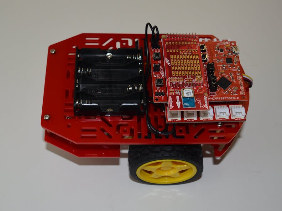
Their are several options to mount your hardware. If you are using the MSP430F5529 LaunchPad it fits well by using the standoffs and included screws and the LaunchPads mounting holes. You can also use double sided tape or glue to apply hardware directly to the chassis.
Now you have a functional remote controller.
Open up Energia and copy the code into a blank sketch. You can save it as MSP430Racerbot.ino.
/* MSP430Racerbot.ino
*
* MSP430 LaunchPad + Grove I2C Mini Motor Driver v1.0 + CC110L BoosterPack
*
* The recommended robot chassis to use is the Adafruit Mini Robot Rover or
* Magician Chassis
*
* The default I2C address of the Grove Mini I2C Motor Driver v1.0 is 0xC4
* and 0xC0. To work with the LaunchPad we need to perform a bitwise right
* shift of one bit (ex. 0xC0 >> 1) which will make the new addresses used
* in this program 0x60 and 0x62
*/
/**
*  WirelessTest - test transceiver sketch using AIR430Boost FCC driver.
*  Copyright (C) 2012-2013 Anaren Microwave, Inc.
*
*  This library is free software; you can redistribute it and/or
*  modify it under the terms of the GNU Lesser General Public
*  License as published by the Free Software Foundation; either
*  version 2.1 of the License, or (at your option) any later version.
*
*  This library is distributed in the hope that it will be useful,
*  but WITHOUT ANY WARRANTY; without even the implied warranty of
*  MERCHANTABILITY or FITNESS FOR A PARTICULAR PURPOSE.  See the GNU
*  Lesser General Public License for more details.
*
*  You should have received a copy of the GNU Lesser General Public
*  License along with this library; if not, write to the Free Software
*  Foundation, Inc., 51 Franklin Street, Fifth Floor, Boston, MA  02110-1301  USA
*
*  This example demonstrates usage of the AIR430BoostETSI library which uses
*  the 430Boost-CC110L AIR Module BoosterPack created by Anaren Microwave, Inc.
*  and available through the TI eStore, for the European Union.
*
*  ----------------------------------------------------------------------------
*
*  Note: This file is part of AIR430Boost.
*
*  ----------------------------------------------------------------------------
*
*  Description
*  ===========
*
*  Each radio will send a message consisting of: 1 byte counter, 5 byte static
*  text. The counter will count from 0 to 9 and will rollover. Each radio will
*  wait in receive mode for approximately one second. Upon receiving data, or
*  timeout of one second, the radio receive function will return. If valid data
*  was received, the radio's receiverOn() method will return the number of bytes
*  that were received. In this example, the data can be monitored on the serial
*  port (please refer to printTxData() and printRxData() functions).
*
*  ----------------------------------------------------------------------------
*
*  This example assumes that two BoosterPacks will be used to showcase the
*  wireless radio communication functionality. This same code should be
*  programmed to both LaunchPad development kits.
*
*  This BoosterPack relies on the SPI hardware peripheral and two additional
*  GPIO lines for SPI chip-select and GDO0 for packet handling. They use pins 18
*  and 19 respectively.
*
*  In the default configuration, this BoosterPack is not compatible with an
*  external crystal oscillator. This can be changed, if necessary, and would
*  require reconfiguration of the BoosterPack hardware and changes to the
*  AIR430BoostFCC library. Refer to the BoosterPack User's Manual if necessary.
*
*  For complete information, please refer to the BoosterPack User's Manual available at:
*  https://www.anaren.com/air/cc110l-air-module-boosterpack-embedded-antenna-module-anaren
*
*  To purchase the 430Boost-CC110L AIR module BoosterPack kit, please visit the TI eStore at:
*  https://estore.ti.com/430BOOST-CC110L-CC110L-RF-Module-BoosterPack-P2734.aspx
*/
// The AIR430BoostFCC library uses the SPI library internally. Energia does not
// copy the library to the output folder unless it is referenced here.
// The order of includes is also important due to this fact.
#include
#include
#include
#include "SparkFunMiniMoto.h"  // Include the MiniMoto library
// -----------------------------------------------------------------------------
/**
*  Global data
*/
// Data to write to radio TX FIFO (60 bytes MAX.)
unsigned char txData[6] = { 'S', 'A', 'i', 'r', '!', '\0' };
// Data to read from radio RX FIFO (60 bytes MAX.)
unsigned char rxData[6] = { 'S', 'S', 'S', '\0', '\0', '\0' };
// Create two MiniMoto instances, with different address settings.
MiniMoto motor0(0xC4 >> 1); // A1 = 1, A0 = clear CH1
MiniMoto motor1(0xC0 >> 1); // A1 = 1, A0 = 1 (default) CH2
int duty = 0;
// -----------------------------------------------------------------------------
// Debug print functions
void printTxData()
{
Serial.print("TX (DATA): ");
Serial.println((char*)txData);
}
void printRxData()
{
/**
*  The following illustrates various information that can be obtained when
*  receiving a message. This includes: the received data and associated
*  status information (RSSI, LQI, and CRC_OK bit).
*/
Serial.print("RX (DATA, RSSI, LQI, CRCBIT): ");
Serial.print("(");
Serial.print((char*)rxData);
Serial.print(", ");
Serial.print(Radio.getRssi());
Serial.print(", ");
Serial.print(Radio.getLqi());
Serial.print(", ");
Serial.print(Radio.getCrcBit());
Serial.println(")");
}
// -----------------------------------------------------------------------------
// Main example
void setup()
{
// The radio library uses the SPI library internally, this call initializes
// SPI/CSn and GDO0 lines. Also setup initial address, channel, and TX power.
Radio.begin(0x01, CHANNEL_4, POWER_MAX);
// Setup serial for debug printing.
Serial.begin(9600);
// join i2c bus (address optional for master)
Wire.begin();
Serial.println("Robot is listening...");
/**
*  Setup LED for example demonstration purposes.
*
*  Note: Set radio first to ensure that GDO2 line isn't being driven by the
*  MCU as it is an output from the radio.
*/
pinMode(RED_LED, OUTPUT);     // initialize the RGB LED
pinMode(GREEN_LED, OUTPUT);   // initialize the RGB LED
digitalWrite(RED_LED, LOW);   // set the LED off
digitalWrite(GREEN_LED, LOW); // set the LED off
}
void loop()
{
digitalWrite(GREEN_LED, HIGH);
delay(20);
digitalWrite(GREEN_LED, LOW);
// Turn on the receiver and listen for incoming data. Timeout after 1 seconds.
// The receiverOn() method returns the number of bytes copied to rxData.
if (Radio.receiverOn(rxData, sizeof(rxData), 1000) > 0)
{
/**
*  Data has been received and has been copied to the rxData buffer provided
*  to the receiverOn() method. At this point, rxData is available. See
*  printRxData() for more information.
*/
digitalWrite(RED_LED, HIGH);
printRxData();                  // RX debug information
if(rxData[0] == 'F'){
Serial.println("Forward!");
if(rxData[1] == 'S'){
motor0.MotoDrive(20);
motor1.MotoDrive(20);
}
else if(rxData[1] == 'F') {
motor0.MotoDrive(100);
motor1.MotoDrive(100);
}
//driveMotor(0x60); // left wheel HIGH
//driveMotor(0x62); // right wheel HIGH
}
else if(rxData[0] == 'L'){
Serial.println("Left Turn!");
if(rxData[1] == 'S'){
motor0.MotoDrive(20);
motor1.MotoStop();
}
else if(rxData[1] == 'F'){
motor0.MotoDrive(100);
motor1.MotoStop();
}
//stopMotor(0x60);  // left wheels LOW
//driveMotor(0x62);  // right wheels HIGH
}
else if(rxData[0] == 'R'){
Serial.println("Right Turn!");
if(rxData[1] == 'S'){
motor0.MotoStop();
motor1.MotoDrive(20);
}
else if(rxData[1] == 'F'){
motor0.MotoStop();
motor1.MotoDrive(100);
}
//driveMotor(0x60);  // left wheels HIGH
//stopMotor(0x62);   // right wheels LOW
}
else if(rxData[0] == 'B'){
Serial.println("Reverse!");
if(rxData[1] == 'S'){
motor0.MotoDrive(-20);
motor1.MotoDrive(-20);
}
else if(rxData[1] == 'F'){
motor0.MotoDrive(-100);
motor1.MotoDrive(-100);
}
}
else{
Serial.println("Stop!");
motor0.MotoStop();
motor1.MotoStop();
//stopMotor(0x60);  // left wheels LOW
//stopMotor(0x62);   // right wheels LOW
}
}
digitalWrite(RED_LED, LOW);
}
//This function will drive the DRV8830 motor driver
//found on
void driveMotor(byte addr)
{
Serial.println("begin drive tx");
Wire.beginTransmission(addr); // transmit to device at device i2c address
Serial.println("address");
Wire.write(0x01);             // sends first bit
Wire.write(0x80);             // sends one byte
Serial.println("before stop");
Wire.endTransmission(addr);       // transmit to device at device i2c address
Serial.println("end of transmission");
Wire.beginTransmission(addr); // stop transmitting
Wire.write(0x00);             // sends first bit
Wire.write(0xFE);             // sends one byte
Wire.endTransmission(addr);       // stop transmitting
Serial.println("end of transmission");
delay(100);
}
// Stop the motor by providing a heavy load on it.
void brakeMotor(byte addr)
{
Serial.println("begin brake tx");
Wire.beginTransmission(addr); // transmit to device at device i2c address
Wire.write(0x00);             // sends first bit
Wire.write(0x03);             // sends one byte
Wire.endTransmission();       // stop transmitting
Serial.println("end of transmission");
delay(100);
}
// Coast to a stop by hi-z'ing the drivers.
void stopMotor(byte addr)
{
Serial.println("begin stop tx");
Wire.beginTransmission(addr); // transmit to device at device i2c address
Wire.write(0x01);             // sends first bit
Wire.write(0x00);             // sends one byte
Wire.endTransmission();       // stop transmitting
Serial.println("end of transmission");
delay(100);
}
Add a new tab for SparkFunMiniMoto.h.
Add a new tab for SparkFunMiniMoto.cpp
STEP 7 - Program the controllerOpen a new sketch in Energia and save it as RacerbotWirelessController.ino.
Open a new tab called Pitches.h.
This is a very complex system but done relatively easily thanks to the modular hardware of the TI LaunchPad and intuitive software of Energia. Additionally you can add more sensors to the Racerbot to add features and capabilities that can teach important mechatronics concepts.


_3u05Tpwasz.png?auto=compress%2Cformat&w=40&h=40&fit=fillmax&bg=fff&dpr=2)

Comments