

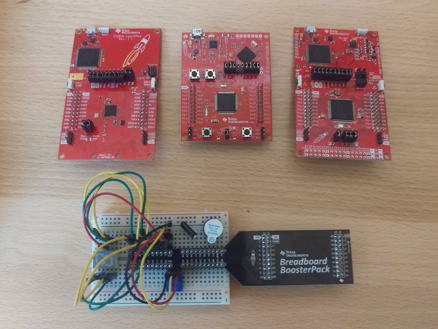
Hardware components | ||||||
 |
| × | 1 | |||
| × | 1 | ||||
 |
| × | 1 | |||
 |
| × | 1 | |||
Software apps and online services | ||||||
 |
| |||||
We are going to introduce the TI LaunchPad development kit using some basic circuits. The TI LaunchPad is a microcontroller kit that you can use to create embedded projects. In this workshop we will use the MSP430P401R LaunchPad but any LaunchPad will work. We will use the Energia IDE version 18 or Energia inside of CCS Cloud for the software development.
First let's talk a bit about the LaunchPad.
This workshop is based off of the examples provided in the Sidekick Basic Kit for TI LaunchPad. You can use this kit to replicate the examples or acquire the components individually. The examples can be found at www.energia.nu/sidekick If you don't have the Sidekick Basic Kit for TI LaunchPad, you can also use the Sidekick Basic Kit for Arduino V2 which has most of the components to complete the lab exercises.
The Sidekick Basic kit for LaunchPad includes
- 1x 400 Tie-Point Breadboard
- 1x Breadboard Adapter BoosterPack (not included in Arduino version)
- 5x Green LED
- 5x Red LED
- 1x RGB Common Anode LED
- 10x Ceramic Capacitor 10nF
- 10x Ceramic Capacitor 100nF
- 5x Aluminum Capacitor 100uF
- 10x Resistor 330 ohm
- 10x Resistor 1K ohm
- 10x Resistor 10K ohm
- 1x Tilt Switch
- 1x Thermistor
- 1x Photoresistor (photocell)
- 1x Diode (1N4004)
- 1x Piezo Buzzer
- 5x Button
- 5x Switch
- 2x Potentiometer with knob
- 1x Small DC Motor (1x Servo in Arduino version)
- 1x 7 Segment Single Digit Display (SA39-11SRWA – datasheet) (not included in Arduino version)
- 1x 8-bit Shift Register (SN74HC595N – datasheet) (not included in Arduino version)
- 2x NPN Transistor (not included in Arduino version)
- 1x Analog Temperature Sensor (LM19CIZ/NOPB – datasheet) (not included in Arduino version)
- 5x Jumper Wire Long
- 20x Jumper Wire Short
- 1x Sidekick Quick Start Guide
- 1x Sidekick Manual
Breadboard circuits can be hard to debug. Make sure you are making careful, proper connections. One misplaced wire can cause unexpected behavior or frustration. If you run into a wall, disconnect everything and start over.
The code is listed at www.energia.nu/sidekick#examples. To load the example library into Energia IDE version 18, use the library manager. You can also get the zip file from www.energia.nu/sidekickcode
Pre-lab (MSP432)Open up Energia IDE. You should get a window like this.
If you would like to adjust the font size, add line numbers, and collapse code, go to File -> Preferences and tick the options you would like.
Next we need to select the correct board we are using. By default MSP430 boards are preloaded but any other types will need to be installed in the board manager. For the MSP432 LaunchPad, go ahead and click Tools -> Board -> Board Manager...
This will open up a screen where you can install the MSP432 board package
Now you can change the board to the MSP-EXP432P401R by going to Tools -> Board -> MSP432.
Next make sure you have any appropriate drivers for your LaunchPad so your computer can communicate with the LaunchPad over the USB cable. In the case of the MSP432P401R, windows users who are using Energia may need a driver. You can find it at http://energia.nu/guide/guide_windows/ under the MSP432P401R section. Mac users shouldn't need anything but you can refer to the http://energia.nu/guide/guide_macosx/ guide if something isn't working. Windows MSP432 Driver: http://energia.nu/files/xds110_drivers.zip
You should be able to select the Serial Port for your LaunchPad from Tools->Serial Port and be good to go. If you have multiple COM ports available you can usually select the highest one. The one with UART is what we want.
Pre-lab (MSP430F5529)Open up Energia IDE. You should get a window like this.
If you would like to adjust the font size, add line numbers, and collapse code, go to File -> Preferences and tick the options you would like.
Next we need to select the correct board we are using. By default MSP430 boards are preloaded but any other types will need to be installed in the board manager. You can double check you have the latest MSP430 board pack, click Tools -> Board -> Board Manager...
This will open up a screen where you can install the MSP430 board package
Now you can change the board to the MSP-EXP430F5529LP by going to Tools -> Board -> MSP-EXP430F5529LP.
Next make sure you have any appropriate drivers for your LaunchPad so your computer can communicate with the LaunchPad over the USB cable. In the case of the MSP430F5529, windows users who are using Energia may need a driver. You can find it at http://energia.nu/guide/guide_windows/ under the MSP432P401R section. Mac users shouldn't need anything but you can refer to the http://energia.nu/guide/guide_macosx/ guide if something isn't working. Windows MSP430F5529LP Driver: http://energia.nu/files/ezFET-Lite.zip
You should be able to select the Serial Port for your LaunchPad from Tools->Serial Port and be good to go. If you have multiple COM ports available you can usually select the highest one. The one with UART is what we want.
Pre-lab (CCS Cloud)If you would like to use the online IDE CCS Cloud you can follow these instructions to set up your LaunchPad. You can go to dev.ti.com to access CCS Cloud IDE. You will need a myTI account and will need to download the browser extension and TI Cloud Agent to your computer.
Lab 0: Blinkhttp://energia.nu/guide/sidekick/sidekick_blink/
This lab involves making sure your LaunchPad environment is set up correctly. You only need your LaunchPad.
Lab 1: Fade RGB LEDhttp://energia.nu/guide/sidekick/sidekick_fadergbled/
Please pause and use the code found at the sidekick page.
This lab will get you started with the breadboard. You will be connecting an RGB LED to your LaunchPad. The MSP432 LaunchPad also has one on board. This is another example of using an OUTPUT.
More about TI LaunchPadOk great we should be all set up with our LaunchPad. Let's take a closer look at what the LaunchPad is all about. Take a quick pause before we move on to Lab 2.
Lab 2: Push Buttonhttp://energia.nu/guide/sidekick/sidekick_pushbutton/
Please pause and use the code found at the sidekick page.
This lab will cover using a push button as an INPUT. You will actuate an LED using a button press.
Lab 3: Multiple LEDs - (Skip to save time)http://energia.nu/guide/sidekick/sidekick_blinkmultiple/
Please pause and use the code found at the sidekick page.
Lab 3 will let you hook up multiple LEDs that can be controlled by your LaunchPad. You will be doing the same exercise with a shift register in Lab 4, so you can immediately skip to that if you understand how to directly control multiple outputs and want to save time. You can always come back later if you finish early. You can also just watch the video to get a summary of the example.
Lab 4: Shift Registerhttp://energia.nu/guide/sidekick/sidekick_shiftregister/
Please pause and use the code found at the sidekick page.
This lab will give you a chance to use an integrated circuit. The shift register gives your LaunchPad more output pins. This can let you control more things (more LEDs for example). You will control 8 LEDs and make a binary counter.
Lab 5: Piezo Buzzerhttp://energia.nu/guide/sidekick/sidekick_piezobuzzer/
Please pause and use the code found at the sidekick page.
Lab 5 will let you play some sound with a buzzer. Making sound can be useful as an audio indicator. You will learn how to play a basic melody with the buzzer.
Lab 6: Potentiometerhttp://energia.nu/guide/sidekick/sidekick_potentiometer/
Please pause and use the code found at the sidekick page.
This lab will give you a chance to play with a variable resistor. The potentiometer is used in knobs and other control schemes to give an analog input. You will use the potentiometer to play a tone and turn on an LED when a threshold is crossed.
Lab 7: Photoresistor - (Skip to save time)http://energia.nu/guide/sidekick/sidekick_photoresistor/
Please pause and use the code found at the sidekick page.
This lab uses another variable resistor that changes its value based on light exposure. This is helpful for when you want something to happen based on when a room is light or dark (turn on and off a light for example). You will change the light exposure on the photocell to affect an LED.
If you need to save time you can skip to Lab 8 and come back later. We already did a variable resistor in Lab 6 so the concept is similar in Lab 7.
Lab 8: Spin the Motor/ServoIf you have a DC Motor: http://energia.nu/guide/sidekick/sidekick_spinmotor/
Please pause and use the code found at the sidekick page.
In this lab you can spin the small motor with a transistor. Motors are useful in a wide variety of projects that require movement and automation.
If you have a Servo: http://energia.nu/guide/sidekick/sidekick_spinservo/
Please pause and use the code found at the sidekick page.
In this lab you can hook up a servo and make it spin. Servos have a gearbox that can be controlled digitally. They are great for robots and a variety of projects that require movement and automation.
Lab 9: Temperature Sensor (Skip to save time)http://energia.nu/guide/sidekick/sidekick_temperature/
Please pause and use the code found at the sidekick page.
In this lab you will compare using a temperature sensor and a thermistor, which is a temperature sensitive resistor. You will get greater accuracy by using a temperature sensor, but sometimes all you need to measure is relative temperature changes.
If you need to save time you can skip to Lab 10 and come back later. In this circuit we are just reading the value from the sensors through the serial monitor. You will see the data change by touching the sensor to introduce heat.
Lab 10: 7 Segment Displayhttp://energia.nu/guide/sidekick/sidekick_sevensegmentdisplay/
Please pause and use the code found at the sidekick page.
In this lab you will hook up a seven segment display to your LaunchPad to display numbers.


Comments