


Hardware components | ||||||
| × | 1 | ||||
| × | 1 | ||||
| × | 1 | ||||
| × | 1 | ||||
Software apps and online services | ||||||
| ||||||
 |
| |||||
Working with microcontrollers is fun until they stop working!
Recently, I was working with an industrial circuit. The circuit and MCU worked flawlessly during testing. So, I designed the PCB and ordered it from JLCPCB. Upon arrival, I uploaded the code to the MCU and ran some basic tests. The whole circuit was working great! (Note that during this basic test, I was powering the PCB using a bench power supply.)
But, after powering from the PCB using the onboard buck module (5V@20A), the MCU seems to have stopped working! No matter how many times I try to reset or reboot the circuit, the MCU won't run. All the voltages, connections, and codes were perfectly fine.
Even weirder, powering the PCB using an external bench power supply works without an issue! At first, I thought it was the buck module, so I swapped it with a new one, but the problem stayed the same! So what was causing the issue? It took me almost 2 days to find that a different fuse configuration inside the microcontroller was the culprit.
This is a problem anyone can face, especially if you are planning to become a professional PCB designer from a hobbyist.
Why does this matter, and what are fuses? In this Instructables, I will try to cover some basics and how I eventually solved the issue.
Theories (microcontroller Family)A microcontroller or MCU has been one of the greatest inventions, and with the advancement of semiconductor technology, you can get a powerful microcontroller for a few cents.
A microcontroller is a cool device that can be used to build all sorts of hardware projects, robots, and embedded systems. A common, and perhaps the most popular, example is the Arduino Uno, which runs on the ATMEGA328P chip from the AVR (Advanced Virtual RISC) family.
For simpler projects, the ATMEGA328P might be overkill; a better alternative is the ATTINY1614. Did you know you can program this chip with the same Arduino code in Arduino IDE? The ATTINY1614 is cheaper, smaller, and has 14 pins.
The ATtiny1614 excels in the AVR family because:
- Supports one-wire code upload using UPDI (Unified Program and Debug Interface)
- It has an internal 20 MHz oscillator (an external oscillator can also be added)
- has 16KB Flash (for your code), 2KB SRAM (for processes), and 256 bytes of EEPROM (for non-volatile storage)
- can work on coin cell battery (working voltage 1.8V to 5.5V)
- 12 programmable General-purpose pins (GPIO)
- ADC, Timers, USART, SPI, I2C, and so much more
With all these advantages, it was a no-brainer for me to use it in one of my circuits.
More Theories - the FUSESAs much as you like a microcontroller, a lack of in-depth knowledge can lead to weird behavior, delayed production, and a lot of wasted time debugging.
Such as the fuses inside a microcontroller. Fuses are simple configuration bits at the very hardware level. Think of it as switches buried inside the microcontroller that are non-volatile (do not lose information when powered down) and do not change their state during programming.
What do they do?Fuse sets some crucial aspects of the chip's hardware, like
- Determining whether the microcontroller uses an internal oscillator or an external?
- Setting the level of the brown-out detector, which resets a microcontroller when the supply voltage drops below the threshold.
- Configuring the reset pin to be used as a GPIO.
- Power-on to code execution delay.
- Locking the chip.
- and more.
- 0x00 WDTCFG (Watchdog configuration)
- 0x01 BODCFG (BOD configuration)
- 0x02 OSCCFG (Oscillator configuration)
- 0x04 TCD0CFG (Timer counter type D configuration)
- 0x05 SYSCFG0 (System configuration 0)
- 0x06 SYSCFG1 (System configuration 1)
- 0x07 APPEND (Application code end)
- 0x08 BOOTEND (Boot End)
- 0x0A LOCKBIT (Lock bits for UPDI)
But we will look into two fuses specifically:
- at 0x01, which is BODCFG (Brown out detector configuration)
- at 0x06, which is SYSCFG1 (system configuration 1 (startup time setting))
Enough with theories, let's see how these fuses are related to my headache!
The CulpritThe PCB is powered by a 65W adapter. The Adapter supplies 20V at 65W. This 20V is lowered to 5V using a 20A switching buck module, as marked using the red circle. This 5V powers the MCU and other circuitry.
To find out the issue mentioned previously, I connected an oscilloscope probe to the power pins of the MCU to measure the voltage changes across the pins. After the power is turned on, the voltage quickly reaches 5V. As you can see from the diagram (2nd picture), the final output is a smooth, stable 5V. There is very little noise and distortion, so what is happening?
If we zoom in (3rd picture), we can see that the output takes some time to reach the full voltage(5V). It was about 8-10ms, a very short pulse, but it was the main culprit!
Why does this matter? Now we come to the star of the show - the fuse at the 0x06 position (offset). This is the SYSCFG1 or system configuration 1 fuse.
What is System configuration 1 fuse?
It sets the start-up time setting, basically it selects the start-up time between power-on and code execution. This was the fuse that was causing the weird issue on my PCB. The available configurable values are:
- Value --- Description
- 0x0 --- 0 ms
- 0x1 --- 1 ms
- 0x2 --- 2 ms
- 0x3 --- 4 ms
- 0x4 --- 8 ms
- 0x5 --- 16 ms
- 0x6 --- 32 ms
- 0x7 --- 64 ms
I am not entirely sure what the default value is set by the manufacturer, but some sources say it's 4-8ms. What it means is that the code execution starts only 4ms after the board is powered. During this period, the supply voltage needs to be very stable. In my case, the voltage was taking too long (about 10-12ms) to reach the stable 5 volts.
This, along with the Brown-out detector (fuse), created an unstable state where the IC won't execute the program even with proper supply voltage.
To solve this, we just need to change the system configuration 1 fuse to a higher value. I set the fuse at 0x05, which corresponds to 16ms start-up.
To change the 0x06 fuse of the ATtiny1614, use this code on platformio.ini:
upload_flags =
--fuses
"6:0x05" ; startup set to 16ms
Now, the ATtiny waits for at least 16ms before starting to execute the code. And within that time, my supply voltage has already reached a stable 5V.
After thorough testing, the bug was gone, and the IC was working perfectly.
Another Useful fuseWhat is a Brown-out detector?
A brown-out detector is a built-in safety feature in microcontrollers that continuously monitors the supply voltage, and if the voltage drops below a safe threshold, then the BOD holds the ATtiny chip in a reset state. Thus, safeguarding the IC from corruption of its flash and EEPROM. On the ATtiny1614, the BOD register is located at 0x01.
If you look at the available BOD levels from the datasheet, there are 8 configurable BOD levels:
- 0x0 (1.80V)
- 0x1 (2.15V)
- 0x2 (2.60V)
- 0x3 (2.95V)
- 0x4 (2.20V)
- 0x5 (3.70V)
- 0x6 (4.00V)
- 0x7 (4.30V)
I guess the MCU ships with 4.3V as the default BOD level. Which means the MCU will only work in a 5V system. That is fine, but the MCU's operating voltage can be as low as 1.8V! Therefore, the chip should work fine even at 1.8V.
But, since the BOD is set to 4.3V, you cannot use the chip on a circuit that runs on, let's say, 3.3V! What it means is that if you supply an ATtiny1614 with 3.3V and the BOD level is set to 4.2V, the IC will be in a reset state, and you won't be able to use it!
A simple change in the fuse (from 0x7 to 0x4) will allow the MCU to operate without an issue at much lower voltages. Now, this is a great hack worth learning!
To change the 0x01 fuse of the ATtiny1614, use this code in platformio.ini
upload_flags =
--fuses
"1:0b00000101" ; BOD level set at 4.3V
I used a binary value (0b00000101) because BOD comes with other features, like once/continuous monitoring. Changing the BOD voltage only uses the three leading bits of the binary value.
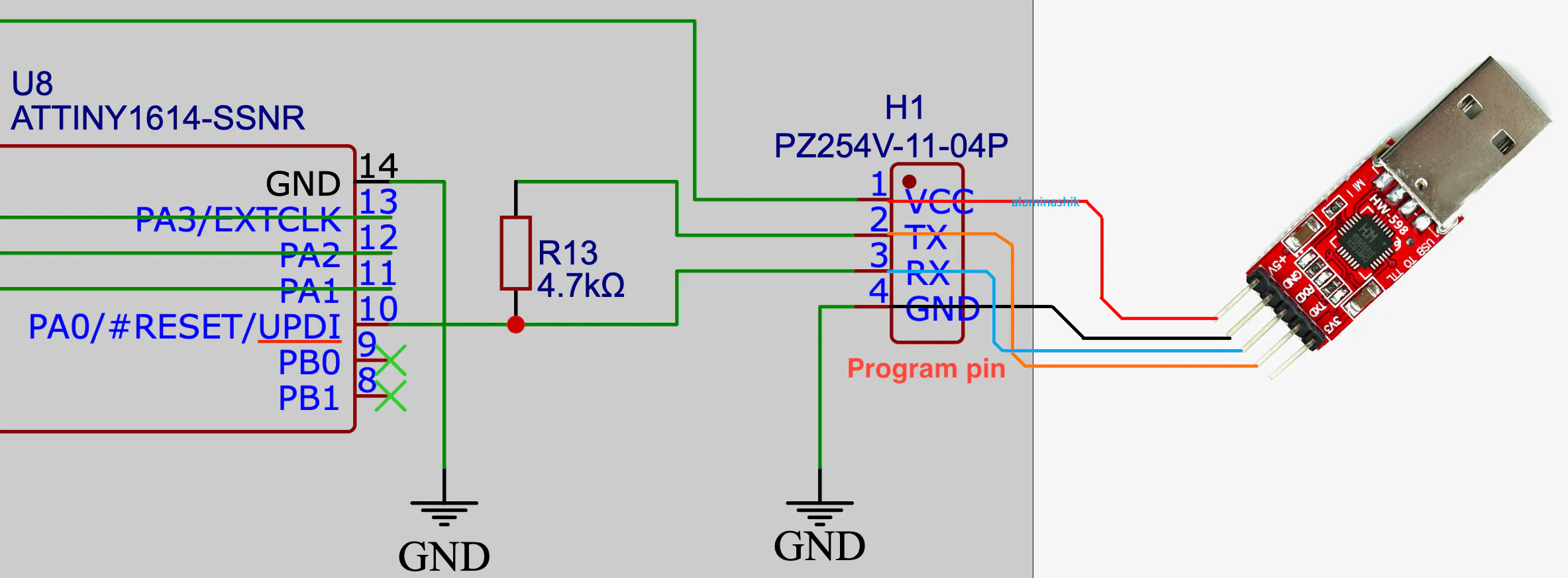
How to Burn a Fuse on a MicrocontrollerChanging a fuse is not done by the code (C or C++ sketch), but by using an external programmer like jtag2updi or USB-to-TTL. To program or change fuse settings, connect the wires as shown in the schematic.
Fuses are set prior to or during the code uploading process. To change the fuse using Arduino IDE, follow these steps:
- Use the Correct Core: You need to ensure you have a modern, compatible board package installed in your IDE, such as megaTinyCore on GitHub.
- Configure in IDE: In the Arduino IDE, use the Tools menu to select your desired clock speed, operating voltage (BOD), and pin assignments.
- Burn Fuses: Click Burn Bootloader in your IDE. Even though the ATtiny1614 does not use a typical bootloader, this specific command is the mechanism the IDE uses to safely write the fuse bytes to the chip.
I often use PlatformIO on VS Code for my embedded projects. So, here are the configurations on platformio.ini for uploading code along with fuse settings on ATtiny1614.
[env:ATtiny1614]
platform = atmelmegaavr
board = ATtiny1614
framework = arduino
upload_protocol = custom
upload_port = /dev/cu.usbserial-001 ;change this to COM port for windows
upload_speed = 230400
build_flags = -DF_CPU=20000000L ;set at 20MHz
upload_flags =
-t
uart
-u
$UPLOAD_PORT
-b
$UPLOAD_SPEED
-d
$BOARD
--fuses
"1:0b00000101 2:0x01 6:0x05 8:0x00" ; BOD:1.8v BOD:enabled startup:16ms
upload_command = ~/.platformio/penv/bin/python3 -u ~/.platformio/packages/framework-arduino-megaavr-megatinycore/tools/prog.py $UPLOAD_FLAGS -f$SOURCE -a write
monitor_speed = 9600Huge shoutout to JLCNC for sponsoring this post. JLCCNC is basically JCLCPCB, but for metal and 3D printing materials.
JLCCNC now offers custom metal CNC for everyone at an affordable price, starting at just $1. The best thing is that you can get very small and very precise shapes using their 5-axis CNC machines.
Click on the link below to get a coupon worth $123 at: https://jlccnc.com/?from=alaminashik


Comments