/*
Derived from non-blocking mode Stepper Driver example by Laurentiu Badea
Parts required:
- Arduino Uno
- L298N Stepper Motor Controller Module, to drive BLDC. (Jaycar XC-4492)(Nb. LEDs L3 and L3 are reversed with respect to Motor B output pins)
- Protoneer Arduino CNC Shield V3 with Pololu A4988 Stepper Motor Driver Carrier fitted, to drive stepper motor.
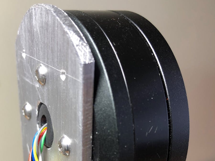
- DC Brushless Motor (BLDC) (funtobuyonline GBM6324-180T appears to be internally wired as though 3-phase stepper motor).
(Refer http://www.aerodesign.de/peter/2001/LRK350/index_eng.html and http://www.aerodesign.de/peter/2001/LRK350/Paper_from%20_Wroclaw.html)
- 4 wire stepper motor (eg 12V NEMA 17).
- 2 or 3 cell LiPO or NiMH battery.
- Switch in series with battery.
- Pot delay on A5 because A0 is reserved by CNC Shield. Used for speed control of BLDC motor
- Pot delay on A4 connected to pot mounted on stepper motor to provide position feedback.
When the brush of the pot wipes past the extremes of the variable resistor the voltage will float, so values selected for this pot must be much higher than 0.
- Pot delay on A3 controls speed of rotation of the stepper motor
Michael Barr in January 2019
*/
#include <Arduino.h> // Required to drive stepper motor
// Motor steps per revolution. Most steppers are 200 steps or 1.8 degrees/step
#define MOTOR_STEPS 200
#define RPM 10
#define MICROSTEPS 1 // Microstepping mode. If you hardwired it to save pins, set to the same value here.
#define DIR 5
#define STEP 2
#define ENABLE 8 // optional (just delete ENABLE from everywhere if not used)
// Generally, you should use "unsigned long" for variables that hold time
// The value will quickly become too large for an int to store
unsigned long previousMillisA3 = 0; // will store last time stepper motor was at extreme end of its arc
unsigned long previousMillisBLDC0 = 0; // stores when BLDC moved to phase 0
int potA5 = 50;
unsigned long difference =0;
const int highPotA5 = 100;
// Defines pins numbers. Wire BLDC to pins on CNC shield which are not used because not using Y and Z motors
const int BLDC1 = 3; // pin labelled Y STEP
const int BLDC2 = 4; // pin labelled Y DIR
const int BLDC3 = 6; // pin labelled Z STEP
int potA3; // Defines variables
int potA4,directionLinkage2; // Defines variables
/*
* Choose one of the sections below that match your board
#include "DRV8834.h"
#define M0 10
#define M1 11
DRV8834 stepper(MOTOR_STEPS, DIR, STEP, ENABLE, M0, M1);
*/
#include "A4988.h"
#define MS1 10
#define MS2 11
#define MS3 12
A4988 stepper(MOTOR_STEPS, DIR, STEP, ENABLE, MS1, MS2, MS3);
// #include "DRV8825.h"
// #define MODE0 10
// #define MODE1 11
// #define MODE2 12
// DRV8825 stepper(MOTOR_STEPS, DIR, STEP, ENABLE, MODE0, MODE1, MODE2);
// #include "DRV8880.h"
// #define M0 10
// #define M1 11
// #define TRQ0 6
// #define TRQ1 7
// DRV8880 stepper(MOTORS_STEPS, DIR, STEP, ENABLE, M0, M1, TRQ0, TRQ1);
void setup() {
Serial.begin(115200);
// declare the BLDC pins as outputs
pinMode(BLDC1, OUTPUT);
pinMode(BLDC2, OUTPUT);
pinMode(BLDC3, OUTPUT);
stepper.begin(RPM, MICROSTEPS);
stepper.enable();
// set current level (for DRV8880 only). Valid percent values are 25, 50, 75 or 100.
// stepper.setCurrent(100);
// Serial.println("START");
}
void loop() {
rotateStepper(); // Rotate 4 wire stepper motor
rotateBLDC(); // Rotate 3 wire BLDC motor
// Serial.println();
}
// Function for rotating stepper motor
void rotateStepper(){
// Linkage 2 stepper motor speed
int potA3 = analogRead(A3); // Reads the potentiometer
potA3 = map(potA3,0,1023,5,360); // Converts the read values of the potentiometer from 0 to 1023 into an angle (0 to 360 degrees )
unsigned long currentMillisA3 = millis(); // Get current time
// Rotate stepper motor until pot is rotated 70 degrees and then rotate back to 0 degrees
int potA4 = analogRead(A4); // Reads the potentiometer
potA4 = map(potA4,0,1023,0,360); // Converts the read values of the potentiometer from 0 to 1023 into an angle (0 to 360 degrees )
// The value selected here must be substantially above zero, as immediately less than zero is 360, which confuses the motor and me
if (potA4 <=80) {
// Serial.print(" potA4 <=80"); // Pot angled to side
directionLinkage2 = 0;
}
else if (potA4 >=185) { // Pot angled to other side
// Serial.print(" potA4 >=185");
directionLinkage2 = 1;
}
if (directionLinkage2 == 0 && currentMillisA3 - previousMillisA3 >= potA3) {
// Serial.print(" rotating out");
stepper.rotate(2);
previousMillisA3 = currentMillisA3;
}
else if (directionLinkage2 == 1 && currentMillisA3 - previousMillisA3 >= potA3) {
// Serial.print(" rotating back");
stepper.rotate(-2);
previousMillisA3 = currentMillisA3;
}
}
// Function for rotating BLDC motor
void rotateBLDC() {
potA5= analogRead(A5); //Read input from analog pin potA5 and store in potA5
potA5= map(potA5, 0, 1023,30,110); //map potA5 to minimum and maximum
// Serial.print("potA5:");
// Serial.print(potA5);
unsigned long currentMillis = millis();
difference = currentMillis - previousMillisBLDC0;
// Serial.print(" difference = ");
// Serial.print(difference);
if (potA5 >= highPotA5) { // Turn off BLDC when BLDC pot is near zero resistance
digitalWrite(BLDC1, LOW);
digitalWrite(BLDC2, LOW);
digitalWrite(BLDC3, LOW);
// Serial.println(" off");
}
else if (difference >= potA5 * 6) {
previousMillisBLDC0 = currentMillis;
// Serial.println(" 6");
}
else if (difference >= potA5 * 5) {
digitalWrite(BLDC1, HIGH);
digitalWrite(BLDC2, HIGH);
digitalWrite(BLDC3, LOW);
// Serial.println(" 5");
}
else if (difference >= potA5 * 4) {
digitalWrite(BLDC1, HIGH);
digitalWrite(BLDC2, LOW);
digitalWrite(BLDC3, LOW);
// Serial.println(" 4");
}
else if (difference >= potA5 * 3) {
digitalWrite(BLDC1, HIGH);
digitalWrite(BLDC2, LOW);
digitalWrite(BLDC3, HIGH);
// Serial.println(" 3");
}
else if (difference >= potA5 * 2) {
digitalWrite(BLDC1, LOW);
digitalWrite(BLDC2, LOW);
digitalWrite(BLDC3, HIGH);
// Serial.println(" 2");
}
else if (difference >= potA5) {
digitalWrite(BLDC1, LOW);
digitalWrite(BLDC2, HIGH);
digitalWrite(BLDC3, HIGH);
// Serial.println(" 1");
}
else {
digitalWrite(BLDC1, LOW);
digitalWrite(BLDC2, HIGH);
digitalWrite(BLDC3, LOW);
// Serial.println(" 0");
}
}


_ztBMuBhMHo.jpg?auto=compress%2Cformat&w=48&h=48&fit=fill&bg=ffffff)


Comments