
Hardware components | ||||||
 |
| × | 1 | |||
| × | 1 | ||||
| × | 1 | ||||
| × | 1 | ||||
| × | 1 | ||||
Not so long ago I got a vintage Toshiba HX-MU901 music keyboard in a pretty good condition. Although I am not a musician (I try hard, but...). I have always been interested in electronics technologies for music. In fact, when I was a teenager, I developed the software Simphony for MSX-1 computers, and later on I composed some classical-like musical pieces with the Amiga 2000 computer (no, you definitively do not want to listen to then).
The HX-MU900 is a MSX-AUDIO cartridge which allows music playing in a MSX computer, using the Toshiba HX-MU901 keyboard. It is very simple but works quite well. The keyboard is sturdy and has no key sensitivity (which for my playing capabilities is not that really a problem :-). I own a Kaway XS-1 vintage synthesizer, the own which I used with my Amiga 200, and I wanted to give it a try with the HX-MU901 keyboard. And for such task I needed a MIDI converter, which is the goal of this project.
THE DEVICE
My main objective with this project was making a fast prototype, trading off cost and size. This is the reason for using Adafruit components (in any case, the cost is very reasonable). The only difficult issue is wiring. After some not-so-easy search, I found a document with the wiring schematics (by Ton Valkenburgh). The keyboard is, basically, a matrix of 8 input rows (IN0-IN7) and 10 output columns (OUT0-OUT9), totaling 18 lines. Fortunately, the Feather M0 has precisely 18 free pins for I/O, in addition to the serial port needed for MIDI communication. The way to read this type of matrices is by using pull-up resistors for the inputs. For this reason I enable internal pull-ups when reading IN lines. The final wiring is as follows:
WARNING: GPIO#13, in Feather M0 boards is also internally connected to a red LED. This produces some "phantom" key presses when scanning the keys corresponding to OUT5. In order to avoid this, it is mandatory to remove this LED or its associated resistor from the board. I damaged the LED when desoldering, but it made no harm to the board.
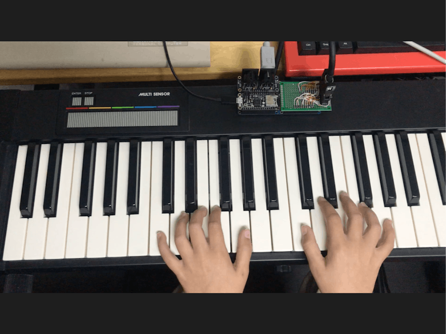
With a PCB breadboard and a little of patience you can prepare a board for making the connections from a male IDC-20 to the Feather M0 pins. In this first incarnation of the board (the one shown in the pictures) I just used two pin headers, because I did not had a male IDC-20 at hand. If you do this, pay attention when connecting the keyboard female IDC-20 connector. You can find the result in the following picture. Do not bother to criticize the result, because I am not the "best" when soldering. But it does work, which is what matters.
The final assembling is very straightforward. Just plug the Feather M0, the FeatherWing MIDI, and the wiring board onto the Feather Quad 2x2. The result is as follows:
THE PROGRAM
The concept is very simple. We periodically poll the state of the different keyboard keys. If we detect any change, we send either a MIDI noteOn (key pressed) or noteOff (key released) with the corresponding note. And then we continue polling. In this way we can detect any simultaneous pressing of the keys (however the receiving device might support only a number of them). The full code is available at GitHub in the attachments section.
NOTE: this same schema can be used to read any kind of matrix keyboard.
I will comment the most relevant parts of the code. Let's start with the important data structures.
The in and out arrays correspond to the input and output pins. The keys array stores the logical values of the matrix keyboard (0 = key pressed, 1 = key released). The chan boolean array contains true for those keys that have changed state (from pressed to released or viceversa). Last, the notes array stores the MIDI note corresponding to each keyboard key. In this case, the first 8 columns correspond to the white and black keys, and the 2 last columns correspond to the multi-sensor keys (colored pads which are touch sensitive).
The reading procedure is typical of this kind of matrix circuits. The idea is to sequentially activate the outputs, and then for each one make the reading of the different inputs sequentially. Output activation is achieved by configuring the corresponding port as output and setting its value to low. Input reading is achieved by configuring the corresponding port as input and enabling its internal pull-up resistor. A little wait cycle in the order of 0.05ms is needed in order for all the signals to get stationary. Then a digital read of the port is executed, whose value is used to update the corresponding cells of the chan and keys arrays. Once the read has been finished, the internal pull-up resistor is disabled. When we finish with a given output, we configure its port back to input.
The procedure to send the corresponding MIDI values is very simple. For this task we will use the fantastic Arduino MIDI library by Forty Seven Effects. We have to distinguish two different cases: a) sending note values because of pressing a key; and b) sending control commands because of pressing the multi-touch. In the first case we only need to check which keys have changed state and the send a noteOn or noteOff depending on the state of the keyboard matrix. As the keyboard has no key sensitivity we send a constant pressure value of 127 to the MIDI channel 1.
In the second case we only need to check which pads of the multi-sensor have changed state and then send the corresponding MIDI commands. We use the MIDI Program Change, which is usually used to change the timbre of the sound (instrument). The global variable program contains the value of the currently selected instrument. If you press the yellow pad, the value of program is reduced by 5 units. If you press the green pad, the value of program is reduced by 1 unit. If you press the blue pad, the value of program is incremented by 1 unit. If you press the violet pad, the value of program is incremented by 5 units.
THE RESULT
I consider that the goal has been achieved in a reasonably good way, with a Bill of Materials which is not costly. You can watch my little daughter testing the system.


Comments