/* ATtiny85 - Advanced Traffic Stop Light - Version 0.1.0 - 2020-02-18
* Copyright (c) 2020 Matt Rude <matt@mattrude.com>
*
* *********************************************************************************
*
* This is a Advanced Traffic Stop Light program written for an ATtiny85 using
* Arduino IDE.
*
* The program was written for an ATtiny85 using Arduino IDE and the 'ATTinyCore'
* board found at: https://github.com/SpenceKonde/ATTinyCore
*
* For more on the ATtiny85, see: https://www.microchip.com/wwwproducts/en/ATtiny85
*
* The ATtiny85 was programed with the external programer, and is running is at a
* clock speed of 1MHz (internal).
*
* The circuit is powered by an external DC buck converter running at 5v.
*
* *********************************************************************************
*
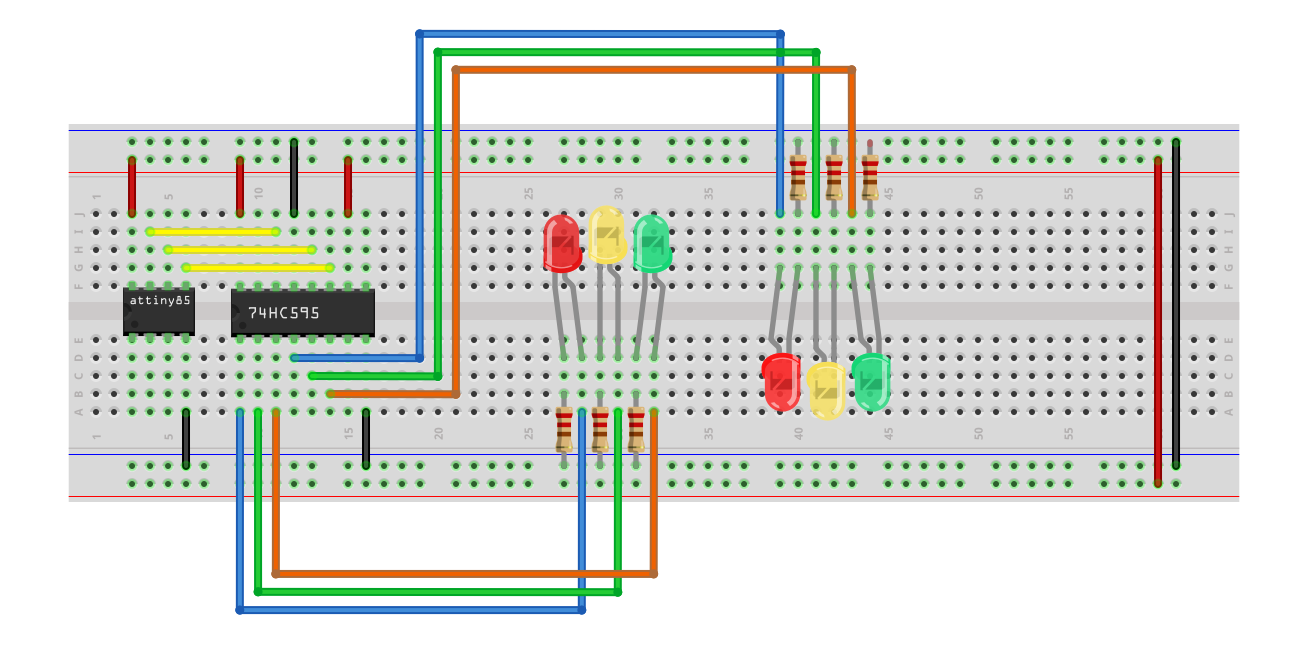
* Required Hardware:
*
* - 1x 1330 ATtiny85-20pu
* - 1x 74HC959 Shift Register
* - 2x Red LED
* - 2x Yellow LED
* - 2x Green LED
* - 6x 220 ohm Resistors
* - 1x Large Breadboard
* - 20x Jumper Wires
*
* Simplified ATtiny85 Pinout:
* (Note: the dot next to the Reset pin represents the dot on the chip.)
* ______
* Reset - |. | - +5v
* A3 - 3 - | | - 2 - A1
* A2 - 4 - | | - 1 - PWM
* GND - |______| - 0 - PWM
*
* 74HC959 Shift Register Pinout:
* (Note: the dot next to the Q1 pin represents the dot on the chip.)
* ______
* Q1 - |. | - +5v
* Q2 - | | - Q0
* Q3 - | | - DS
* Q4 - | | - OE
* Q5 - | | - STCP
* Q6 - | | - SHCP
* Q7 - | | - MR
* GND - |______| - Q7S
*
* *********************************************************************************
*
* Changelog:
*
* 2020-02-18 - 0.1.0 - Initial Release.
*
* *********************************************************************************
*
* MIT License
*
* Copyright (c) 2020 Matt Rude <matt@mattrude.com>
*
* Permission is hereby granted, free of charge, to any person obtaining a copy
* of this software and associated documentation files (the "Software"), to deal
* in the Software without restriction, including without limitation the rights
* to use, copy, modify, merge, publish, distribute, sublicense, and/or sell
* copies of the Software, and to permit persons to whom the Software is
* furnished to do so, subject to the following conditions:
*
* The above copyright notice and this permission notice shall be included in all
* copies or substantial portions of the Software.
*
* THE SOFTWARE IS PROVIDED "AS IS", WITHOUT WARRANTY OF ANY KIND, EXPRESS OR
* IMPLIED, INCLUDING BUT NOT LIMITED TO THE WARRANTIES OF MERCHANTABILITY,
* FITNESS FOR A PARTICULAR PURPOSE AND NONINFRINGEMENT. IN NO EVENT SHALL THE
* AUTHORS OR COPYRIGHT HOLDERS BE LIABLE FOR ANY CLAIM, DAMAGES OR OTHER
* LIABILITY, WHETHER IN AN ACTION OF CONTRACT, TORT OR OTHERWISE, ARISING FROM,
* OUT OF OR IN CONNECTION WITH THE SOFTWARE OR THE USE OR OTHER DEALINGS IN THE
* SOFTWARE.
*
* *********************************************************************************
*/
// This is the amount of time, in seconds, to wait between light changes.
int changeDelay = 30;
// Declare the shift register pins
int clockPin = 0; // Connected to SHCP (pin 11) on the 74HC595.
int latchPin = 1; // Connected to STCP (pin 12) on the 74HC595.
int dataPin = 2; // Connected to DS (pin 14) on the 74HC595.
void setup() {
// Set the three shift register pins to output.
pinMode(clockPin, OUTPUT);
pinMode(latchPin, OUTPUT);
pinMode(dataPin, OUTPUT);
// Start with the clockPin set to a LOW state
digitalWrite(clockPin, LOW);
}
void loop() {
// Set the Both directions to Red
digitalWrite(latchPin, LOW);
shiftOut(dataPin, clockPin, MSBFIRST, 0b00100010);
digitalWrite(latchPin, HIGH);
delay((changeDelay*100)/8);
// Set the first directions to Green and the second to Red
digitalWrite(latchPin, LOW);
shiftOut(dataPin, clockPin, MSBFIRST, 0b10000010);
digitalWrite(latchPin, HIGH);
delay(changeDelay*100);
// Set the first directions to Yellow and keep the second direction Red
digitalWrite(latchPin, LOW);
shiftOut(dataPin, clockPin, MSBFIRST, 0b01000010);
digitalWrite(latchPin, HIGH);
delay((changeDelay*100)/4);
// Set the Both directions to Red
digitalWrite(latchPin, LOW);
shiftOut(dataPin, clockPin, MSBFIRST, 0b00100010);
digitalWrite(latchPin, HIGH);
delay((changeDelay*100)/8);
// Set the first directions to Red and the second to Green
digitalWrite(latchPin, LOW);
shiftOut(dataPin, clockPin, MSBFIRST, 0b00101000);
digitalWrite(latchPin, HIGH);
delay(changeDelay*100);
// Set the first directions to Yellow and keep the second direction Red
digitalWrite(latchPin, LOW);
shiftOut(dataPin, clockPin, MSBFIRST, 0b00100100);
digitalWrite(latchPin, HIGH);
delay((changeDelay*100)/4);
}


_3u05Tpwasz.png?auto=compress%2Cformat&w=40&h=40&fit=fillmax&bg=fff&dpr=2)


Comments