Creating the wired remote controller was relatively straightforward after Chris showed me a genius way of doing it with paper. We drew what half of the controller could look like on a piece of paper, using our hands as measurements for how big it should be. We then got buttons and triggers and placed them on the picture we drew and traced them. In order to transfer this to Adobe Illustrator with correct placements and measurements, I drew a box around the controller and used a ruler to measure the distance from an element to the box. The .AI file is included below.
1 / 3 • Cardboard test cutout
In terms of wiring, the idea was to simply map the push buttons on my solderless breadboard controller onto this new controller.
Back view of all the wiring
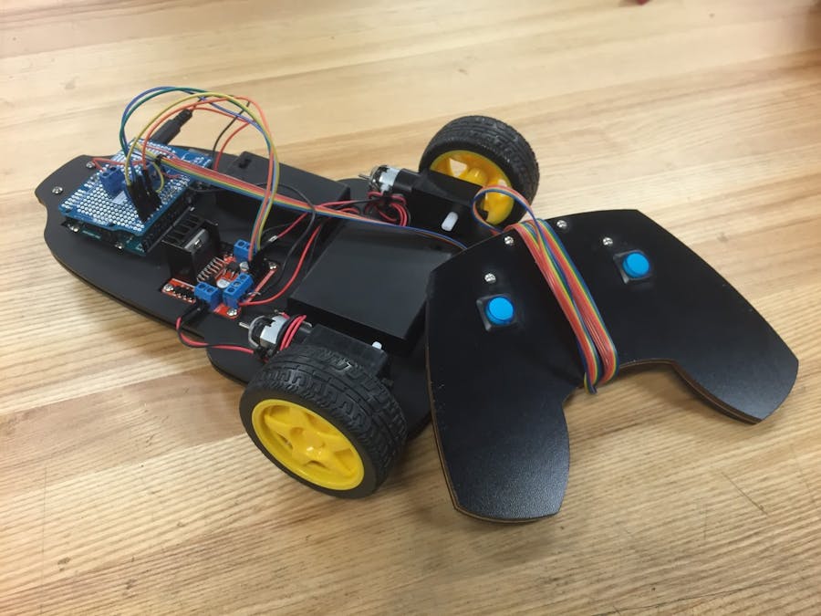
The way this remote control works with the attached code is that the left and right triggers move the left and right wheels forward, respectively. Holding both down makes both wheels go forward. The left and right buttons reverse left and right, respectively. Holding both buttons down reverses both wheels at the same time.
Additionally, to make the remote controller modular, I soldered screw terminals onto an Arduino protoshield and screwed in the stranded leash to the shield. This way, using the leash simply requires putting the protoshield onto the Arduino.
Protoshield with screw terminals for the leash
Chassis modification
Per Chris and Michael's advice, I changed my chassis edges from sharp corners to rounded corners. This makes the car safer and harder to break if dropped because the point of contact against another object increases with rounded corners, thereby making the vehicle stronger.
Old chassis on the left vs. new chassis on the right. Notice the round sides.
Fastening it all together
I used 0.5 inch screws and nuts to fasten the caster, Arduino Uno, and L298 to the chassis in order to ensure they wouldn't fall out under any conditions. The battery packs already are embedded into the chassis pretty tightly with these measurements, so I didn't add any adhesives. I can always add double-sided tape at the bottom of each if necessary. To fasten the leash, I ziptied it against the chassis body at the back of the car so that the point of tension isn't on the wires if the leash is pulled.
1 / 2 • Side view. Double-sided tape between the layers plus fasteners.
Demos
Problems
Problems I faced during this portion were mainly with how I soldered and the trigger switches. A soldering tip that Chris gave me that came in handy was to add solder to both things you're soldering first before connecting. Then, simply touch the two and heat the solder that's already on both components to easily solder them together. Also, unsoldering can be super annoying. When I soldered the wires to the triggers, I wrapped them around the outlets. My wiring was wrong at that time, so in order to unsolder I had to continually heat up the metal and un-wind the wire with the soldering iron itself.
My car couldn't pass the ramp in class because the chassis was too low for its length. It got stuck at the top of the ramp. I need to solve this for the next iteration. I'm thinking of either moving the wheels below the chassis to give the car more height, or shortening the chassis.
Lessons
I was going to originally stay with the solderless breadboard remote control until Chris opened my eyes to thinking about the whole user experience. There needed to be a better way to drive the RC car. Using a solderless breadboard with tiny pushbuttons is a horrible experience. Making this remote controller served as a reminder to think about all aspects of the user experience, not just the product.
Solid core wires should also be used in cases where wires won't move. For example, they should be used as the underlying connections on a protoshield. On the other hand, stranded wires should be used in cases where wires will move like the remote controller's leash. Solid core wires break easily when they move a lot.
There are two remote control paths in this file because the controller has two layers. One layer has smaller holes for the push buttons so that they can be fastened in.
// Matt Chiang// Des Inv 90-2 Fall 2015// Which L298 IN is hooked up to which digital pin on the Arduino?// If you change these, make sure one IN for each motor is linked to a PWM digital pin.// Motor 1intIN1=7;// IN1 on the L298 is linked to digital pin 7intIN2=6;// pwm// Motor 2intIN3=4;intIN4=3;// pwm// The buttons are hooked up to which digital pins?constintrightTrigger=9;// the number of the pushbutton pinconstintleftTrigger=10;constintleftButton=11;constintrightButton=12;// VariablesintrightTriggerState=0;// variable for reading the pushbutton status; 1 on (pressed) 0 off (unpressed)intleftTriggerState=0;intleftButtonState=0;intrightButtonState=0;constintLED=13;voidforward(){digitalWrite(IN1,HIGH);digitalWrite(IN2,LOW);digitalWrite(IN3,LOW);digitalWrite(IN4,HIGH);}voidturnLeft(){digitalWrite(IN1,LOW);// LOW for stoppingdigitalWrite(IN2,LOW);digitalWrite(IN3,LOW);digitalWrite(IN4,HIGH);}voidturnRight(){digitalWrite(IN1,HIGH);digitalWrite(IN2,LOW);// this IN2 could not be working. CHECK IF SOLDERED CORRECTLYdigitalWrite(IN3,LOW);// LOWdigitalWrite(IN4,LOW);}voidreverse(){digitalWrite(IN1,LOW);digitalWrite(IN2,HIGH);digitalWrite(IN3,HIGH);digitalWrite(IN4,LOW);}voidreverseLeft(){digitalWrite(IN1,LOW);digitalWrite(IN2,LOW);digitalWrite(IN3,HIGH);digitalWrite(IN4,LOW);}voidreverseRight(){digitalWrite(IN1,LOW);digitalWrite(IN2,HIGH);digitalWrite(IN3,LOW);digitalWrite(IN4,LOW);}voidbrake(){digitalWrite(IN1,LOW);digitalWrite(IN2,LOW);digitalWrite(IN3,LOW);digitalWrite(IN4,LOW);}voidsetup(){pinMode(IN1,OUTPUT);// Set the pin IN# to behave as an outputpinMode(IN2,OUTPUT);pinMode(IN3,OUTPUT);pinMode(IN4,OUTPUT);// Set up the buttons and triggerspinMode(rightTrigger,INPUT);pinMode(leftTrigger,INPUT);pinMode(leftButton,INPUT);pinMode(rightButton,INPUT);}voidloop(){rightTriggerState=digitalRead(rightTrigger);leftTriggerState=digitalRead(leftTrigger);leftButtonState=digitalRead(leftButton);rightButtonState=digitalRead(rightButton);// Move forward by pressing both triggersif(rightTriggerState==1&&leftTriggerState==1){forward();}elseif(leftTriggerState==1){turnLeft();}elseif(rightTriggerState==1){turnRight();}elseif(leftButtonState==1&&rightButtonState==1){reverse();}elseif(leftButtonState==1){reverseLeft();}elseif(rightButtonState==1){reverseRight();}else{brake();}}


Comments