

Hardware components | ||||||
| × | 1 | ||||
Software apps and online services | ||||||
 |
| |||||
| ||||||
This project shows how to program an Arduino Mega 2560 using Simulink to receive the signals from an R/C receiver.
IntroductionOne common question when working with different robots is how to use an R/C controller to control it. Standard robotics has the R/C receiver send a servo-style pwm signal directly to the servo motors or the motor controller as indicated by the diagram below with Method 1. Many roboticists look to change this relationship by placing a microcontroller in between the R/C receiver and the motors as shown with Method 2. This allows the user to create fly/drive-by-wire programs on the microcontroller where you can for example, design traction control algorithms. You could even take it one step farther by using one of the channels on the R/C Controller to switch the code between different operating modes i.e. R/C control vs. Automated. This example will show how to program an Arduino Mega 2560 using Simulink to receive R/C signals. A second article will be made to demonstrate a drive-by-wire program with a four-wheel vehicle, and will show how to use one of the channels to switch between remote and autonomous modes.
The output of the R/C receiver consists of 4 servo style signals. Servo signals are pulses with a width of about 1-2 ms and a period of about 20 ms. The length of 1 ms is the minimum pulse, 2 ms is the maximum pulse and 1.5 ms is the neutral pulse. There are two types of servo motors, continuous servos and position servos. For a continuous servo, the length of the pulse corresponds to the speed of rotation. For a position servo, the length of the pulse corresponds to the angular position of the servo. When controlling aircraft with an R/C remote, the receiver is connected to position servos.
We recommend completing Getting Started with Arduino Mega 2560 Hardware.
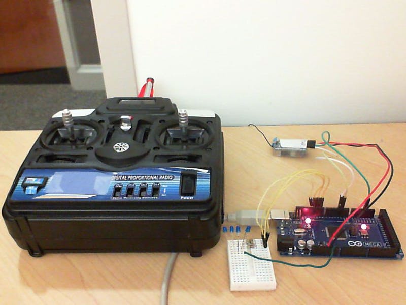
Required HardwareTo run this example you will need the following hardware:
Controller board:
- Arduino Mega 2560 board
- USB cable
Radio Control:
- Generic R/C controller and receiver
Debug Circuit:
- 4x LEDs
- 4x 100 Ohm Resistor
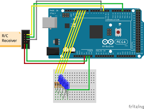
- Connect pins 2, 3, 18, and 19 to the 4 channels on the R/C receiver.
- Supply power to the R/C receiver. I supplied 5V from the Arduino 5V pin to an ESC which then plugged into the receiver.
Download the RC Receive block from the MathWorks File Exchange.
https://www.mathworks.com/matlabcentral/fileexchange/45541-rc-receive-driver-block-for-arduino
Task 3: Setup the EnvironmentSetting up the environment needs to be performed only once per version of MATLAB that you have installed. If you have performed these steps before, please ignore this section.
- Make sure that a compiler is installed. You can set up the compiler by typing (>> mex –setup) at the MATLAB command window. If no compilers show up when you type this command determine which compiler you should use and download from here:http://www.mathworks.com/support/compilers/current_release/For my Windows 7 machine running MATLAB 64-bit, I am using the Windows SDK 7.1compiler, which is free.
- Type (>> targetinstaller) to set up the Arduino
- Setting up the driver block needs to be performed only once. If you change the underlying code in the block, you will need to set up the driver block again.
- To use the custom driver block, 3 files need to be generated;
- sfcn_rcreceive_wrapper.cpp
- sfcn_rcreceive.tlc
- sfcn_rcinterupt.[mex], where [mex] can be mexw32, mexw64, mexmaci64 depending on your OS and version of MATLAB. For my Windows 7 machine using MATLAB 64-bit, the extension is .mexw64.
- Open the rcreceive.slx model.
- Open the “RC Receive” S-function Builder block.
- Click “Build”
- Type (>> modify(‘sfcn_rcreceive’) at the MATLAB Command Window
- Verify that your working directory or “Current Folder” is the folder where the following files are located (i.e. C:\rcdriverblock):
- rcreceive.slx.
- sfcn_rcreceive.[mex]
- sfcn_rcreceive.tlc.
- sfcn_rcreceive_wrapper.cpp.
2. Open the model “rcreceive” if not opened already.
3. Click the “Run” button to enter external mode.
4. If you move the joysticks corresponding to channels 1,2,3 and 4 on pins 2,3,18, and 19, the corresponding values in the Display block and Scope will change. If the values go over 1750, the corresponding LEDs will turn on.
This driver block attaches externally triggered interrupts to the pins that are specified in the block. These interrupts are bidirectionally triggered (i.e. when the input goes from high to low or low to high). The code in this block uses the two triggers to measure the length of the input pulse. As the joystick moves in the up or right direction, the pulse gets larger, and the code returns a larger value.
For more information on this, feel free to check out the following blog, which describes the c implementation of the algorithm in the Arduino IDE:
How to read multiple R/C channels
Future WorkShow how to use the R/C remote with a mobile platform, i.e. drive by wire.


Comments