


Hardware components | ||||||
 |
| × | 1 | |||
 |
| × | 1 | |||
 |
| × | 1 | |||
| × | 1 | ||||
 |
| × | 2 | |||
| × | 2 | ||||
 |
| × | 1 | |||
 |
| × | 1 | |||
| × | 1 | ||||
 |
| × | 1 | |||
| × | 1 | ||||
| × | 1 | ||||
 |
| × | 1 | |||
 |
| × | 1 | |||
 |
| × | 1 | |||
 |
| × | 1 | |||
| × | 1 | ||||
| × | 1 | ||||
Software apps and online services | ||||||
 |
| |||||
 |
| |||||
Hand tools and fabrication machines | ||||||
 |
| |||||
 |
| |||||
 |
| |||||
 |
| |||||
This article is a part of assignment submitted to Deakin University, School of IT, Unit SIT210 - Embedded Systems Development.
IntroductionIndoor plant care in urban environments often relies on guesswork where plants are usually placed near a window and watered when the user thinks it is necessary.
This project improves on manual plant care by creating an embedded microclimate control system. The system uses an ESP32 to collect environmental readings and control physical actuators, while a Raspberry Pi handles MQTT communication, decision making, data logging, plant profiles, email alerts and a local web dashboard.
The goal is to automatically monitor the plant environment and control watering, ventilation, and lighting in a safer and more configurable way.
What the System DoesThe system can:
- Read temperature and humidity using a DHT22 sensor.
- Read light level using a TSL2591 sensor.
- Read soil moisture values.
- Publish ESP32 sensor readings to the Raspberry Pi using MQTT.
- Store readings in a SQLite database.
- Apply plant profile rules to decide control actions.
- Control a fan, water pump, servo vent, and grow light.
- Display readings and actuator states on a Flask dashboard.
- Allow manual control through the dashboard.
- Track daily water usage.
- Apply pump safety limits and failsafe behaviour.
System Architectureblock diagram:
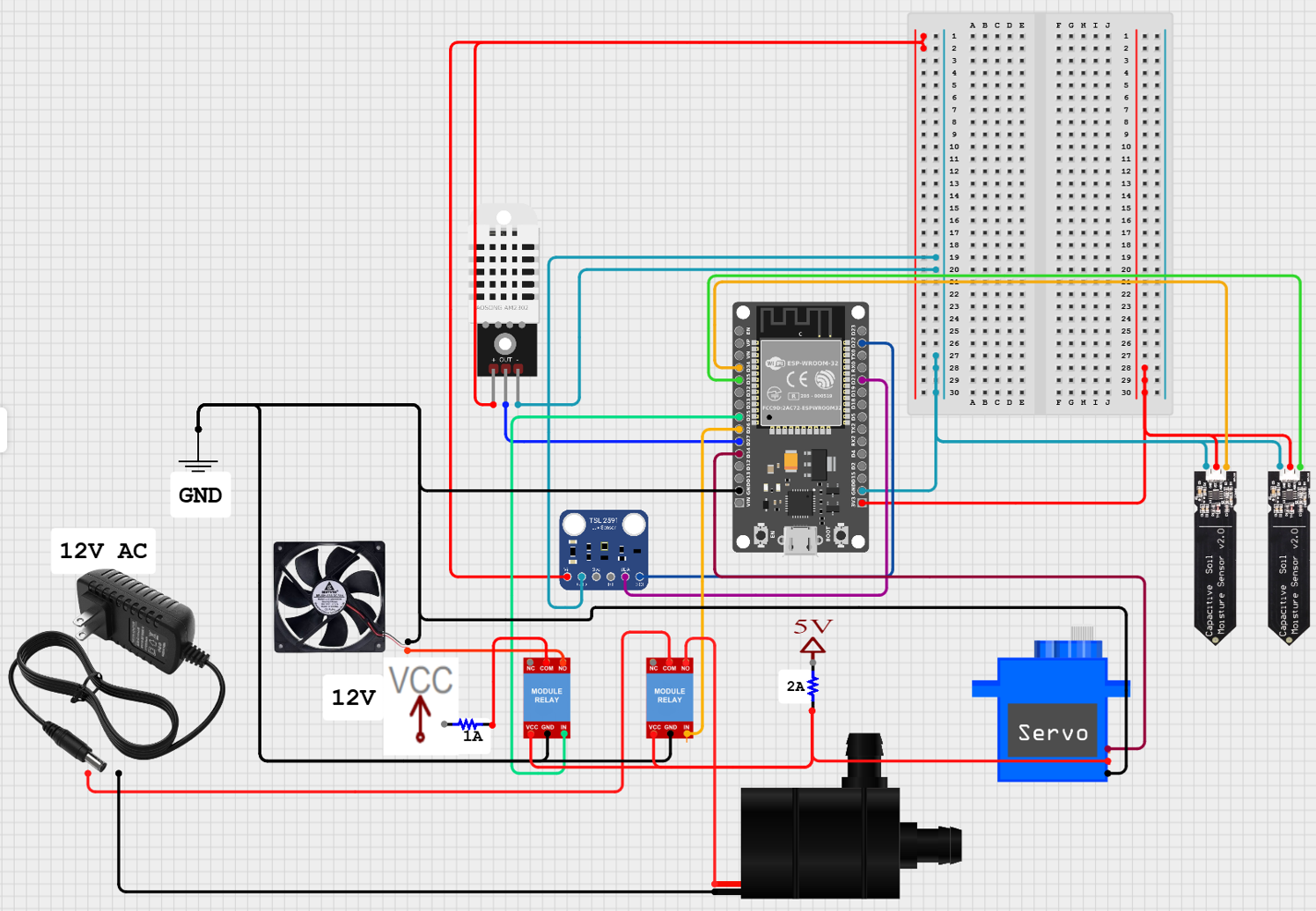
ESP32 wiring
Following the above layout we first want to connect
Step 1: Prepare the ESP32The ESP32 is the main embedded device connected to the sensors and low voltage actuator controls. Before connecting actuators, I first tested the ESP32 by itself using the Serial Monitor to confirm that it could connect to Wifi and communicate with the Raspberry Pi MQTT broker.
Step 2: Connect the DHT22 SensorThe DHT22 is used to measure temperature and humidity inside the plant environment. This sensor provides digital temperature and humidity readings to the ESP32. (make sure you place this inside your enclosure).
DHT22 Pins:
VCC -> 3.3V
GND -> GND
DATA -> ESP32 GPIO27
Step 3: Connect the TSL2591 Light SensorThe TSL2591 is used to measure light level in lux. This helps the system decide whether the grow light should be turned on. The TSL2591 uses the I2C serial communication protocol. This means it only needs two communication wires: SDA for data and SCL for clock. (Make sure this is place in a spot that isn't directly hit by your growlight, either above/blocked path)
TSL2591 Pins:
VIN -> 3.3V
GND -> GND
SDA -> GPIO21
SCL -> GPIO22
Step 4: Connect the Soil Moisture SensorsThe soil moisture sensors are used to estimate how dry or wet the soil is. The soil moisture sensors output an analogue voltage. The ESP32 reads this voltage using its ADC pins and converts it into a digital raw value. This value is then mapped into a soil moisture percentage.(you might need to configure this later yourself in the config.h
Soil Sensor Pins:
VCC -> 3.3V
GND -> GND
AOUT -> GPIO34 and GPIO35
Step 5: Connect the Relay ModulesThe fan and pump are controlled using relay modules. The relay allows the ESP32 to switch a separate power circuit without powering the actuator directly from the ESP32. The relay modules I used are active-high, so the ESP32 sets the relay input pin HIGH to turn the actuator on.
Both Relays Pins:
DC+ -> 5V
DC- -> GND
COM -> 12V in (from PSU)
NO -> 12V out
Fan relay:
IN1 -> GPIO25
Pump relay:
IN1 -> GPIO26
Important: Do not power the pump, fan, or servo directly from the ESP32. Use a suitable external power supply. Also make sure you understand whether your pump uses DC or AC power before wiring it through the relay. (Be sure everything is connected to the correct power source, you can use a multimeter to test connections if needed)
If you wish to use a PSU like I did, make sure you know which pins to use.I would advice getting a proper power source that fits the exact criteria if you aren't comfortable with this.Make sure you find the correct pin layout for your exact PSU, as they can differ between PSU. I used a corsair which has the following pin layouts
(optional, but I would recommend it)
Add a 2A fuse to both the 5V and 12V power supply, to prevent damaging your components if something shorts.
Step 8: Connect the Servo VentThe servo is used to open and close the ventilation flap.
Servo Pins:
VCC -> External 5V
GND -> Common GND
Signal -> GPIO14
The servo should be powered from a suitable 5V supply rather than directly from the ESP32! The servo ground and ESP32 ground must be connected together so that the signal has a common reference.
The ESP32 controls the servo using PWM through the servo library. I also added slower servo movement in software so the vent opens and closes smoothly instead of snapping instantly to the target angle.
You will need a flap to close the vent with too, this will vary depending on your enclosure. (you can block the inlet or outlet to prevent airflow)
Step 9: Connect the Grow Light Using a Smart OutletThe grow light is not controlled directly by the ESP32 or a custom relay circuit. Instead, I used a TP-Link/Kasa smart outlet controlled by the Raspberry Pi over the local network.
This is safer because the grow light uses mains power, and the low voltage embedded circuit does not directly switch mains voltage.The Raspberry Pi sends commands to the smart outlet when the decision engine decides the lamp should turn on or off.
You will need to edit the kasa settings inside config.py on the raspberry pi.
ENABLE_KASA_LAMP = True
KASA_HOST = "local address of your smart strip"
KASA_LAMP_OUTLET_NAME = "your outlet name"
Step 10: Common GroundFor the low voltage DC parts of the circuit, the grounds need to be connected together. This includes:
ESP32 GND
Both relay module
DC-
Servo power supply GND
Fan power supply GND
This allows the ESP32 control signals to work correctly with the relay modules and servo.
Step 11: Connect Smart outlet and growlightConnect your kasa smart outlet to your wifi using the app and kasa smart outlet instructions (These differ depending on kasa outlet).
Finally connect your growlight to the smart outlet and remember which plug it is in if there are multiple. (will add these settings later).
Step 12: Test One Component at a TimeI tested the electronics in stages rather than connecting everything at once.
I would recommend test in this order:
1. Test ESP32 WiFi and Serial Monitor.
2. Test DHT22 temperature and humidity readings.
3. Test TSL2591 light readings.
4. Test soil moisture readings (get dry and wet readings, write down for later).
5. Test fan relay.
6. Test pump relay with a short safe runtime.
7. Test servo vent movement.
8. Test Kasa smart outlet control.
9. Test full MQTT communication between ESP32 and Raspberry Pi.
Step 13: Physical set upFinally the physical set up of the system, you will need to put everything together. This will heavily depend on the enclosure and parts you have, as they most likely differ from mine.
Ideally the growlight should be above the enclosure pointing down into a transparent top, the water reservoir should be seperated from the ESP32, and other electronic components.
There should be two opening for air flow on opposite sides of the enclosure, with a fan on one of the openings, and the vent preferably on the top opening to prevent heat escaping when closed.
Depending on the enclosure you're using you might require cutting a hole in the enclosure, if that's the case I'd recommend using a hole sore that fits the size of your fan.
Update and install mosquitto for MQTT broker:
sudo apt update
sudo apt install mosquitto mosquitto-clients python3-venv git
then:
git clone https://github.com/Mason-D/microclimate-control-system.git
cd microclimate-control-system/rpi_controller
python3 -m venv venv
source venv/bin/activatepip install -r requirements.txt
Then run the controller:python3 main.py
And the dashboard in a separate terminal:python3 dashboard.py
You will then be able to access the dashboard through your web browser on the local network:http://<raspberry-pi-ip>:5000
ESP32 Setup1. Install Arduino IDE
2. Install ESP32 board support
3. Install the required Arduino libraries:
-ArduinoJSON
-PubSubClient
-ESP32Servo
-DHT sensor Library
-Adafruit TSL2591 library
-Ada fruit unified sensor library
4. Open the ESP32 project
5. Change secrets.h.txt to secrets.h (remove.txt)
6. Add WiFi SSID, password, and Raspberry Pi MQTT IP address
7. Upload the code to the ESP328. Open Serial Monitor at 115200 baud
MQTT CommunicationTopics:
greenhouse/sensors ESP32 publishes sensor
readingsgreenhouse/commands Raspberry Pi publishes actuator
commandsgreenhouse/status ESP32 publishes status messages
Testing the Systemsubscribing to MQTT topics on the ESP32
subscribing to MQTT topics on the Raspberry Pi
double check you have properly configured the config.h and config.py files to match your project needs.
Check you have added correct details to secrets.h, and email_secrets.py
DashboardTo add new or edit profile names you will currently need to edit the plant_profiles.JSON
You can either copy paste an existing profile, or rename the existing one to something else.
Code WalkthroughThe code is split into two main parts: the ESP32 code and the Raspberry Pi controller code.
ESP32:
- Reads sensors.
- Publishes sensor readings to MQTT.
- Subscribes to actuator commands.
- Controls fan, pump, and servo vent.
- Applies local safety rules.
Raspberry Pi:- Runs the MQTT broker.
- Receives sensor readings.
- Stores readings in SQLite.
- Applies plant profile rules.
- Sends commands back to the ESP32.
- Hosts the Flask dashboard.
- Sends email alerts.
Code


Comments