

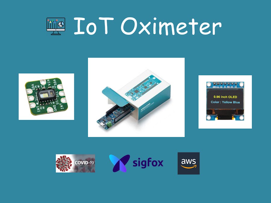
Hardware components | ||||||
| × | 1 | ||||
 |
| × | 1 | |||
 |
| × | 1 | |||
| × | 1 | ||||
Software apps and online services | ||||||
 |
| |||||
| ||||||
 |
| |||||
Hand tools and fabrication machines | ||||||
 |
| |||||
The purpose of this tutorial is to show you how we can simply help our loved ones monitor one of the symptoms of covid-19, namely oxygen saturation (SPO2). An SMS alert system allows us to be warned as soon as the measured SPO2 is below a critical threshold.
The World Health Organization (WHO) said "The oxygen saturation for an healthy patients of any age should be 95% or above." (source).
In this crisis situation, the people who are most at risk are also those who are least comfortable with new technologies. That's why one of the challenges will be to create the simplest possible object: an on/off button and an OLED screen to inform the user. Nothing else. No need for a Wi-Fi connection or Bluetooth pairing, which requires mastery of the smartphone.
Simply switch on the object and place your finger on the sensor for a few seconds. If the oxygen saturation is below the set threshold then an SMS is sent to the indicated phone number(s).
Let's see how to build this simple connected oximeter.
The core of the object will be the Arduino MKRFOX1200 board. It has a reliable footprint and integrates a module communicating via the Sigfox LPWAN network.
Sigfox plays an important role in this project: the network will allow us to communicate in a simple way (no need for pairing, SIM card or internet connection) and at a low energy cost for a better autonomy.
The SMS alert will be sent with every Sigfox message received through Amazon Simple Notification Service (SNS).
The oxygen saturation rate will be measured using Farnell's MAX30102 I2C sensor and a precision-enhancing algorithm from this C library.
The measurement results and data sending information will be displayed on an OLED I2C screen.
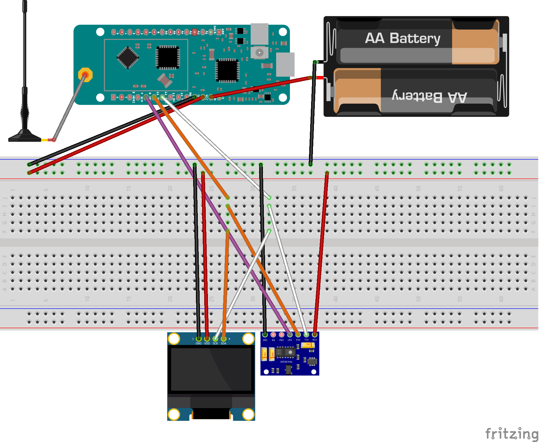
Finally, everything will be connected with jumper wires and a breadboard.
Build the electronicLet's solder headers pin to the INT, GND, VIN, SDA, SCL pins of MAX30102 module:
Here is the schematic:
By default the interrupt (INT) pin of the MAX30102 is connected to the pin 10 of the mkrfox1200. You can choose another one and change the value of the constant oxiInt in the code.
Both the OLED display and the MAX30102 communicate with the I2C protocol. You can interconnect the SDA and SCL pins of the mkrfox with those of the OLED display and MAX30102 via the breadboard. Same for VCC and GND pins.
The external power supply must be between 3.3V and 5V. In this example I use two 1.5V AA batteries. Connect the positive terminal of the battery to the VIN pin and the negative terminal to GND.
Here is the Fritzing preview:
In order to run the MAX30102 driver on the mkrfox1200 board (with SAMD21 MCU) we need to install this great library written by Fraczkiewicz, R.
- Download the files on the repository
- Copy algorithm_by_RF.cpp, algorithm_by_RF.h, max30102.cpp and max30102.h one level above where your Arduino.ino file is located.
- If you wanna use the OLED display then download the SSD1306Ascii library directly from the Arduino library manager.
You can now upload the code in the Arduino.
Sigfox registrationIn order to send the data to Sigfox backend we need to register the device with its unique IDs. We can get them with an Arduino example code.
- Download the "Arduino sigfox for mkrfox1200" library from the Arduino library manager.
- Run the "FirstConfiguration" example code provided by the library.
- On the Serial monitor you will get the device and PAC IDs.
- Enter the informations at https://buy.sigfox.com/activate to activate your contract and then add a new device on the Sigfox backend (go to DEVICE -> new).
- You can check that everything is working by running the FirstConfiguration example code and type a message to send in the serial monitor. You should see the message in the sigfox backend:
The data sent are displayed in Hexadecimal format. We can set a "custom grammar" in order to decode and display them in readable format.
Go the Sigfox backend -> DEVICE TYPE -> click your type -> INFORMATION -> Edit
At the bottom of the page fill the "custom configuration" input field:
spo2::uint:16:little-endian hr::uint:8:little-endian moduleTemp::uint:16:little-endianNow you should be able to see the decoded data under each messages:
We can notice that spo2 is equal to 9985 and module temperature is equal to 1500. This is because we multiple it by 100 in the code in order to remove the comma (float to int conversion).
Sigfox callbackWe need to configure a callback on the Sigfox backend to be able to send SMS when we receive a message.
Go to DEVICE TYPE -> click your device type -> CALLBACKS
Choose AWS IoT. Then click on the Launch stack button to create an Amazon connector. You will need to create an Amazon Web Services account.
Amazon will ask you to enter a payment method when creating the account. Amazon invoices in "pay-as-you-go", meaning that you pay according to what you consume. They offer free services up to a certain limit, so you will not be charged as long as you stay below that limit.
BE CAREFUL of unpleasant surprises. You alone will be responsible for any charges that may be incurred. This being said, let's see how to configure the Sigfox connector in AWS.
Tip: take care to select the good zone corresponding to your country at every steps of the tutorial.
To create the stack choose Template is ready and click Next:
Now you can fill the inputs:
- Stack name: a meaningful name for the connector.
- AWSAccountId: your AWS Account Id (in the navigation bar at the upper right, choose Support, and then Support Center. The account number (ID) appears in the navigation pane on the left).
- External Id: external Id given to you in the Sigfox create callback screen.
- Region: your region.
- Topic Name: topic name you will send data to.
Then click Next, check the I acknowledge that AWS CloudFormation might create IAM resources box and create the stack.
After a few minutes the stack's status should be CREATE_COMPLETE.
Select the AWS CloudFormation stack, click on the Outputs tab and copy the value for ARN Role. Go Back to the Sigfox console and paste the value you copied for ARN Role. Enter the topic name and the region you chose.
Some zones are missing in Sigfox so choose the closest one. For example for me living in France I chose "EU (Frankfurt)" in Sigfox and "Europe (Frankfurt) eu-central-1" in AWS.
Then you can enter the costum payload config:
spo2::uint:16:little-endian hr::uint:8:little-endian moduleTemp::uint:16:little-endianand the Json body:
{"device" : "{device}", "time" : {time}, "data" : "{data}", "moduleTemp": {customData#moduleTemp}, "spo2": {customData#spo2}, "hr": {customData#hr}, "seqNumber" : {seqNumber}, "lqi" : "{lqi}", "linkQuality" : {linkQuality}, "lat" : {fixedLat}, "long": {fixedLng}, "operatorName" : "{operatorName}", "countryCode": {countryCode}, "deviceTypeId": "{deviceTypeId}", "computedLocation" : {computedLocation}}Note: The json must be on the same line in order to be interpretable by AWS.
Finally the Sigfox callback should looks like this:
Now that we have linked our Sigfox backend to our AWS account, let's see how to send an SMS to each received message. It is simple and fast to set up.
Note: BE CAREFUL, sending SMS via Amazon SNS may incur charges. More information is available here.
You need to create a topic in Amazon SNS. Give it a name and create the topic. Then you can create a subscription to your topic: select the topic ARN corresponding to the one you previously created, SMS as protocol and the phone number you want to get the SMS.
Next we need to create a rule that publish messages to our SNS topic when getting those from Sigfox. Go to IoT Core -> Act -> Rules -> Create. Let's name it sigfox_sms_rule.
In my example I send an SMS with the module temperature, spo2 and heart rate:
SELECT moduleTemp,spo2,hr FROM 'sigfox'Next add an Action -> select Send an SNS push notification -> Configure action. We can now set the previously created topic, message format RAW and create a role to grant AWS IoT access:
Finally, you should have something like this:
Create the rule when you are done.
That's it! You can now receive SMS when the spo2 measured by your connected oximeter is below the threshold.
Battery lifeThis connected oximeter is energy autonomous. Let's see how the system consumes energy and estimate the object's autonomy. For this purpose I have connected a precision multimeter in series with the system. The input voltage for testing is 4.2 V.
Here is its consumption waiting for a measurement:
As you can see, its average consumption is 18 mA.
Now let's see how much it takes to send a Sigfox message:
By placing cursors just before and after the message is sent, we can see that the average consumption of a send is 38 mA. The time interval is 7 seconds.
The time of a measurement is on average 15 seconds and the time of a sending is 7 seconds.
Let us note Cm the consumption for a measurement, Cs the consumption for a send and Ct the total consumption for a measurement and send data.
Cm = 15 * 18 = 270 mAs
Cs = 7 * 38 = 266 mAs
Ct = 536 mAs or 536 / 3600 = 0.148 mA
A total consumption of 0.148 mA is obtained for a measurement and send data.
Let's say you are using a battery with a capacity of 2400 mAh.
Battery Life = Battery Capacity in mAh / Load Current in mA
Battery life = 2400 / 0.148 = 16,216 h = 675 days
To sum up, using the oximeter connected once a day with a 2400 mAh battery gives a battery life of almost 2 years.
That's the end of the tutorial!
Feel free to make comments, all ideas are welcome! Thank you for reading my project and take care of yourself.


_3u05Tpwasz.png?auto=compress%2Cformat&w=40&h=40&fit=fillmax&bg=fff&dpr=2)
Comments