

Hardware components | ||||||
 |
| × | 1 | |||
 |
| × | 1 | |||
 |
| × | 1 | |||
 |
| × | 4 | |||
Software apps and online services | ||||||
 |
| |||||
HERE in this article I am going to show how to make a smart irrigation system at home. This is very easy to make and of course its a prototype project which could be modified according to our need. I have made this basically for the beginners or the intermediates. This is an ARDUINO BASED project which makes it user friendly and if you are looking for a project to show some where like science exhibition, final year college project presentation, environmental science project, agricultural project etc. in several field then this is really a good project that you may try. Making cost for this project is also very low.
WHY AUTOMATIC IRRIGATION SYSTEM IS NEEDEDThe benefits of automatic irrigation are:
The benefits of automatic irrigation are:- reduced labor.
- timely irrigation — plants being watered when needed.
- management of higher flow rates.
- accurate cut-off of water compared to manual checking.
- reduced runoff of water and nutrients.
- reduced costs for vehicles used to check irrigation.
PARTS OF THE PROJECT
PARTS OF THE PROJECTTo make and understand it easily we have splatted this project into two main parts.
- MECHANICAL Part
- ELECTRONICS Part
for better explanation we have divided our ELECTRONICS Part into
- Circuit and PCB
- Assemble the electronics components
- ARDUINO coding
Here in this part we will need some PVC sheet to make the chassis, 4 TT gear motors with wheels, 1 submersible pump, one cooldrinks can which is completely optional. you may use anything else to make the water tank. This is considered as the easiest part of this robot. All you need to only cut the PVC sheet and assemble all the components together in a proper way. Here I have attached some pictures on this.
Here I have used 60rpm TTgear motors but you may vary the rpm according to your need. But one tips I want to share that, lower rpm motos are easy to control & they could be shown easily in any resentation. Thats it for this part. now we will move to our next part which is ELECTRONICS PART. Here we will directly enter into the circuit and pcb making part. This could be littlebit tough if you are a fresher in making electronics project but I will explain is as much easier as possible.
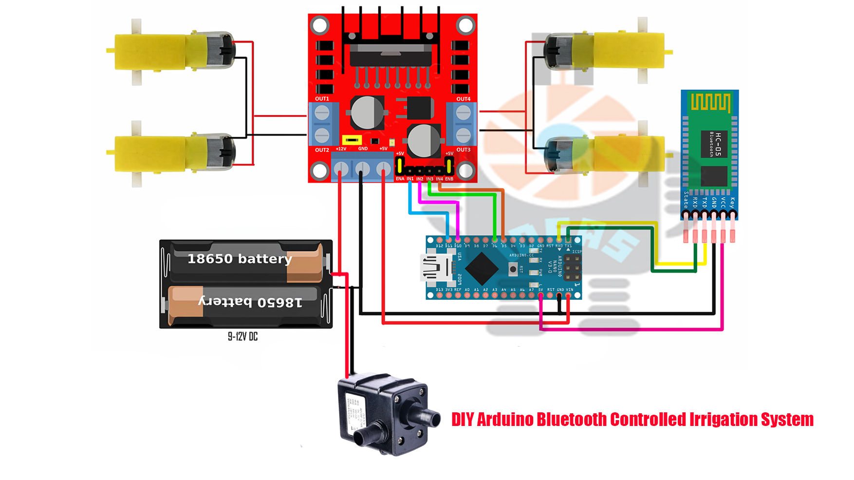
CIRCUIT & PCB MAKINGHere I have attached the circuit or the connection diagram which is very easy to understand and make. Please follow this diagram when you are going to make this project.
This project will work or perform same with or without making pcb but I have made PCb boards for this project. Actually not only for this, I always do prefer making any project using Customized PCB boards. There have obviously some advantages of making any project using PCB boards. like
- Compact Size and Saving of Wire.
- Ease of Repair and Diagnostic. If in case of any damage, it's very easy to check and replace the particular failure components.
- Saving of Time.
- Immune to Movement.
- Tight connections and Short Circuits Avoided.
- Low Electronic Noise.
- Low Cost.
- Reliability.
So I always make PCB BOARD for my every project. As I have already mentioned before I have already attached a circuit diagram with this article so please download that before you are going to connect all of them together. In my case, I have made a customized PCB board from JLCPCB to skip a few steps of wiring and make an easy connection between all the components.$2 for 5pcs PCBs, PCBA from $0, Register to Get Free Coupons here: https://jlcpcb.com/IYB. I really liked the PCB Boards as they are very high in quality.
Now we will make all the components together. But before that please make sure that you have gathered all of them correctly. Here I have enlisted the components and also provided their pictures for your references. Hope this will help you to make this easier.
SO THE COMPONENTS THOSE WILL BE NEEDED ARE- ARDUINO NANO WITH CABLE
- L298N MOTOR DRIVER
- HC-05 BLUETOOTH MODULE
- M4 DIODE
- RED LED
- 78M05 VOLTAGE REGULATOR
- 220uF CAPACITOR
- TERMINAL BLOCKS
- HEADER PINS


_3u05Tpwasz.png?auto=compress%2Cformat&w=40&h=40&fit=fillmax&bg=fff&dpr=2)
Comments