Testing the addressable LEDs on the Explorer Backpack v1
Idea
What is this? A design challenge? I'm fairly new to electronics and creating PCBs. While working on a project using EasyEDA/LCSC/JLCPCB I saw a banner for a contest. I've been wanting to create a development board with a variety of sensors on it. So I decided I'd challenge myself to finally make it. I knew if I had a deadline it would motivate me to get it done. I have to say this is the most complex project I've worked on to date and am really proud of myself for getting it to work.
The contest provided a development board from WCH. The CH32V307V. I nicknamed it the "Centipede" because the microcontroller (CH32V307VCT6) has 100 pins. It has an impressive processor based on RISC-V. With extensions for multiplication, atomic, float and compressed instructions built in. It has a plethora of peripherals and communication protocols. Such as an Analog to Digital Converter (ADC), CAN, Digital to Analog Converter (DAC), Ethernet, I2C, I2S, SPI, UART and USB. These connections come together to create a resourceful tool for newcomers and veteran designers alike.
The WCH CH32V307V-R1 Development Board
This board has a convenient set of "Arduino Uno" style connectors at the heart of the Centipede. These are ideal to create an add-on board to attach to the top. My idea was born: The Explorer Backpack. The intent of this project is to help people learn about interfacing a variety of peripherals. It could be transformed into a decorative light, data logger, TV remote, alarm or a home automation and monitoring system. With a little imagination the Explorer Backpack's possibilities are limitless.
Design
After deciding what features I would bring together, came the challenge of picking out specific parts. I browsed electronics companies like Adafruit, Seeed Studio and SparkFun to determine which sensors are most commonly used. Like most designers I wanted to keep costs low, so I selected components that were mildly priced, but still capable. I was able to locate most of them on LCSC, Digi-Key and Mouser. It's relieving to have multiple suppliers during the "parts shortage" era.
Accelerometer
Addressable LEDs
Flash Memory
Humidity Sensor
IR LED Emitter
IR Signal Decoder
Light Sensor
Microphone
Slide Switch
Speaker and Amplifier
Tactile Switch
Temperature Sensor
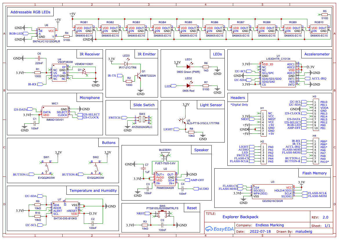
Once I narrowed down all the components, I downloaded all of their respective data sheets. Most companies provide example circuit diagrams and If one was not provided, I looked for an available breakout board.
I meticulously incorporated the selected sensors into my EasyEDA design and created all necessary connections; formatting a clean schematic by grouping components according to their function.
I referred to the data sheets for the microcontroller to ensure proper assignment of the pins to their corresponding peripherals. For example the second set of I2C pins are PB10 (SCL) and PB11 (SDA). Both of these can be found on the middle set of headers.
Please see the attachments section for the full schematic. I've also included the EasyEDA source files on my GitHub.
Layout
To start, I looked at the CH32V307V design files to determine the location of the mounting holes and headers. I wanted to make the board roughly match the size of an Arduino shield (53 x 68mm).
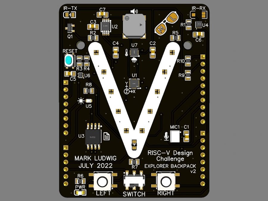
As an homage to the RISC-V processor I placed the addressable LEDs in the shape of a capital V. The sensors and components were put adjacent to their corresponding communication pins for easy routing of the connections.
The Explorer Backpack (Front and Back)
PCB
I sent off my Gerber files to JLCPCB to have the PCBs manufactured. I selected a black solder mask to match the look of the development board. I also ordered a solder paste stencil to make it easier to assemble all those tiny surface mount components. For board nerds there's nothing greater than getting a shipment of PCBs in the mail.
Assembly
Using the bill of materials I created a spreadsheet to help me assemble the board. I then looked at the data sheets for the infrared LED, light sensor and the addressable LEDs. I created a cheat sheet to help me place them in the correct orientation. I used the stencil to apply the solder paste, hand placed all of the components, and then put the board on a small hot plate. Watching solder paste melt is so cool. Am I right?
PCB SMD Assembly Timelapse
Testing
I wanted to make sure all of the components were connected correctly and functioning as intended. I used other development boards such the Arduino Uno and the Raspberry Pi Pico. I'm familiar with their IDEs and toolchains which made it easier for me to to validate my design. The examples are in the Code section of this article.
Success! I was able to load up the GPIO Toggle example and get it to work. The LED on the Explorer Backpack was blinking on and off. Hello World!
RT-Thread OS
Part of the contest is to use the RT-Thread embedded real-time operating system. MounRiver Studio can create a project based on RT-Thread. Examples of the Explorer Backpack LED blinking and the buttons working using RT-Thread are provided in the GitHub repository.
My first program using MounRiver Studio to blink the onboard LED on the Explorer Backpack on pin PA2. This uses a modified version of the GPIO Toggle example.
Testing the addressable LEDs on the Explorer Backpack using the Arduino IDE and the Adafruit Neopixel library on an Arduino Uno. This uses a modified version of the strandtest example sketch.
#include<Adafruit_NeoPixel.h>// Which pin on the Arduino is connected to the NeoPixels?#define LED_PIN 9// How many NeoPixels are attached to the Arduino?#define LED_COUNT 10// Declare our NeoPixel strip object:Adafruit_NeoPixelstrip(LED_COUNT,LED_PIN,NEO_GRB+NEO_KHZ800);// NEO_KHZ800 800 KHz bitstream (most NeoPixel products w/WS2812 LEDs)// NEO_GRB Pixels are wired for GRB bitstream (most NeoPixel products)// setup runs once at startupvoidsetup(){strip.begin();// INITIALIZE NeoPixel strip object (REQUIRED)strip.show();// Turn OFF all pixels ASAPstrip.setBrightness(50);// Set BRIGHTNESS to about 1/5 (max = 255)}// loop runs repeatedly as long as board is onvoidloop(){rainbow(10);// Flowing rainbow cycle along the whole strip}// Some functions of our own for creating animated effects// Rainbow cycle along whole strip. Pass delay time (in ms) between frames.voidrainbow(intwait){// Hue of first pixel runs 5 complete loops through the color wheel.// Color wheel has a range of 65536 but it's OK if we roll over, so// just count from 0 to 5*65536. Adding 256 to firstPixelHue each time// means we'll make 5*65536/256 = 1280 passes through this loop:for(longfirstPixelHue=0;firstPixelHue<5*65536;firstPixelHue+=256){// strip.rainbow() can take a single argument (first pixel hue) or// optionally a few extras: number of rainbow repetitions (default 1),// saturation and value (brightness) (both 0-255, similar to the// ColorHSV() function, default 255), and a true/false flag for whether// to apply gamma correction to provide 'truer' colors (default true).strip.rainbow(firstPixelHue);// Above line is equivalent to:// strip.rainbow(firstPixelHue, 1, 255, 255, true);strip.show();// Update strip with new contentsdelay(wait);// Pause for a moment}}
Audio Out
C/C++
Testing the speaker on the Explorer Backpack using the Arduino IDE on an Arduino Uno. This uses a modified version of the code provided in the resource link at the top of the sketch.
// Resource:// https://create.arduino.cc/projecthub/SURYATEJA/use-a-buzzer-module-piezo-speaker-using-arduino-uno-89df45// The Arduino pin connected to the AUDIO IN on the amplifier (PAM8304)constintbuzzer=A1;// The Arduino pin connected to the ENABLE pin on the ampconstintenable=8;voidsetup(){// Set both pins to outputspinMode(buzzer,OUTPUT);pinMode(enable,OUTPUT);// Turn on the enable pindigitalWrite(enable,HIGH);}voidloop(){tone(buzzer,262);// Middle C in hertzdelay(500);// Delay for 500 mstone(buzzer,294);// D in hertzdelay(500);// Delay for 500 mstone(buzzer,330);// E in hertzdelay(500);// Delay for 500 mstone(buzzer,349);// F in hertzdelay(500);// Delay for 500 mstone(buzzer,392);// G in hertzdelay(500);// Delay for 500 mstone(buzzer,440);// A in hertzdelay(500);// Delay for 500 mstone(buzzer,493);// B in hertzdelay(500);// Delay for 500 mstone(buzzer,523);// C in hertzdelay(500);// Delay for 500 msnoTone(buzzer);// Stop the sound...delay(5000);// ...for 5 sec}
Light Sensor
C/C++
Testing the ambient light sensor on the Explorer Backpack using the Arduino IDE on an Arduino Uno. This uses a modified version of the AnalogInOutSerial example sketch. The value is sent to the Serial Monitor.
// The pin the light sensor is attached toconstintanalogInPin=A0;// Set up the variable for the light sensor valueintsensorValue=0;voidsetup(){// initialize serial communications at 9600 baudSerial.begin(9600);}voidloop(){// read the analog in value:sensorValue=analogRead(analogInPin);// print the results to the Serial Monitor:Serial.print("Light = ");Serial.println(sensorValue);// wait 1000 milliseconds before the next loop for the analog-to-digitaldelay(1000);}
Buttons
Python
Testing the left and right buttons (momentary switches) on the Explorer Backpack using Circuit Python with a Raspberry Pi Pico. The value is sent to the serial monitor and turns on the onboard LED.
Link to my GitHub Repository. It contains the source files for the 3D Printed Case, PCB Assembly, Bill of Materials, Board Previews, EasyEDA files, Gerbers, Photos, Pinout Diagram and Schematic.


Comments