


Hardware components | ||||||
| × | 1 | ||||
 |
| × | 1 | |||
 |
| × | 1 | |||
 |
| × | 4 | |||
Software apps and online services | ||||||
| ||||||
| ||||||
This project demonstrates how to implement a software-based voltage comparator on the STM32F407ZGT6 using the ADC's built-in Analog Watchdog peripheral. A potentiometer provides a variable voltage from 0 V to 3.3 V, and the firmware monitors this voltage against a fixed threshold programmed directly into the Analog Watchdog window registers.
When the potentiometer voltage crosses the threshold, the ADC hardware fires an interrupt, no polling loop involved. The interrupt callback HAL_ADC_LevelOutOfWindowCallback() handles the LED color change immediately, leaving the CPU completely free between crossing events.
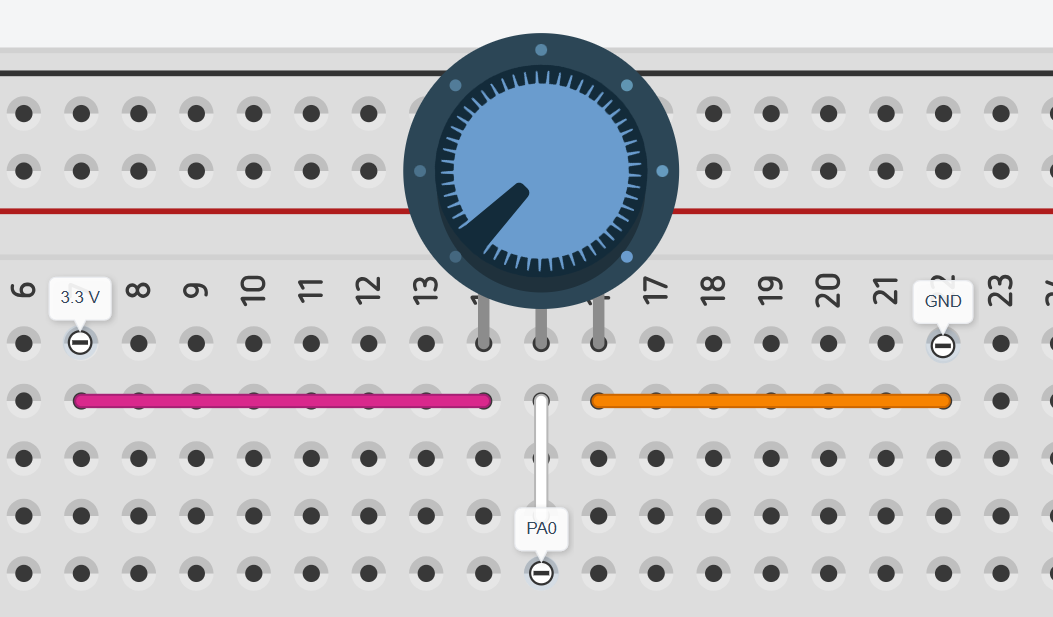
Hardware SetupThe circuit is minimal. The potentiometer's two outer pins connect to 3.3 V and GND, and the wiper (middle pin) connects directly to the ADC analog input on the MCU. A current-limiting resistor is placed in series with the LED.
- Create a new STM32CubeIDE project and select the STM32F407ZGT6 MCU.
- Generate the code. In
main.c, start the ADC in interrupt mode usingHAL_ADC_Start_IT(). Thewhile(1)loop is intentionally left empty because the CPU does nothing between threshold crossings.
Toggle On
Toggle Off
The LED turns on and off at around 1.65V, which is exactly half of the 3.3V supply. The two thresholds (2031 and 2061) are set slightly apart on purpose so the LED doesn't flicker when the voltage is right at the boundary, it only switches when the voltage clearly crosses one side or the other.
ConclusionThis project showed how to use the RT-Spark to monitor a potentiometer voltage and trigger an LED when it crosses a certain level. Instead of constantly checking the voltage in a loop, the microcontroller only reacts when the voltage actually crosses the threshold, which is a more practical and efficient approach.
Note: Some parts of this lab could not be completed as written because the lab guide had inconsistent and incomplete instructions. The schematic shown in the guide did not match the actual hardware setup provided, and certain steps were unclear or missing details needed to follow them properly.



Comments