

Hardware components | ||||||
| × | 1 | ||||
 |
| × | 1 | |||
 |
| × | 3 | |||
 |
| × | 1 | |||
 |
| × | 1 | |||
| × | 1 | ||||
Software apps and online services | ||||||
| ||||||
| ||||||
This project demonstrate how timer interrupts can be used to keep track of time in an embedded system. Instead of using an external LCD module, the project uses the built-in LCD of the RT-Spark board.
The timer interrupt runs every 1 millisecond and continuously updates the hour, minute, second, and millisecond values. Every 100 milliseconds, the LCD is refreshed to show the latest time.
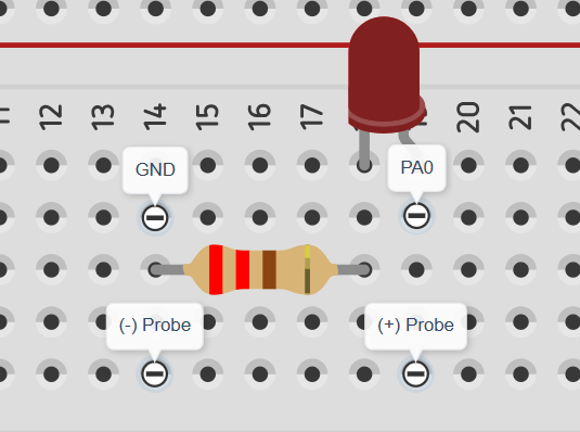
An LED is also used as a visual indicator. It flashes every second and slowly fades out using PWM control. The brightness starts at 100% and decreases to 0% during the first 600 milliseconds of each second.
This project shows how multiple peripherals can work together to create a simple but useful embedded application.
Built-in LCD setupCreate a new STM32 project.Select the STM32F407ZGT6 MCU and keep the default settings.Configure PF9 as GPIO Output.
Generate the code.
Turn on the LCD backlight in the program.
When powered on, the LCD backlight should light up, confirming that the display is receiving power.
LCD backlight testing:LCD Communication Setup
After testing the backlight, the LCD communication interface was configured.
Set PD3 as LCD_RST.Enable FSMC in STM32CubeMX.
Import the LCD libraries.Download the needed header and source files for the built-in LCD setup.
Generate the code and initialize the LCD.
LCD testingSoftware Setup
The built-in LCD of the RT-Spark board was used to display the clock, while timers were configured to handle timekeeping and LED fading.
The timer interrupt runs every 1 ms and performs the following:
- Updates the current time.
- Requests an LCD update every 100 ms.
- Controls LED brightness using PWM.
- Flashes the LED every second.
The display was refreshed every 100 milliseconds, making the clock update smoothly and accurately. A timer interrupt running every 1 millisecond handled the timekeeping in the background, ensuring that the clock remained precise. At the same time, an external LED flashed once every second and gradually dimmed until it turned off, creating a smooth fade-out effect using PWM.
Testing with OscilloscopeAn oscilloscope was used to check the PWM signal generated by the STM32F407ZGT6. The waveform showed that the signal was working correctly and changing as expected. As the PWM duty cycle decreased, the LED became dimmer until it eventually turned off. This confirmed that the timer and PWM settings were configured properly and that the LED fade-out effect was working successfully.
ConclusionThis project successfully created a simple clock using the STM32F407ZGT6 microcontroller and the RT-Spark board's built-in LCD. The system was able to display the elapsed time accurately while using timer interrupts to keep track of time and PWM to create a smooth LED fading effect.


Comments