


Hardware components | ||||||
| × | 1 | ||||
 |
| × | 1 | |||
| × | 3 | ||||
| × | 1 | ||||
 |
| × | 2 | |||
| × | 1 | ||||
| × | 2 | ||||
 |
| × | 1 | |||
Software apps and online services | ||||||
 |
| |||||
| ||||||
This project is a Smart Clothesline Robot, built as a proof of concept for a real-world automated clothesline system.
The idea came from a practical problem. I live in Melbourne, where the weather can change very quickly. There have been times when I left clothes outside to dry, went to university, and came back to find them soaked because it started raining. This project explores how an embedded system could help solve that problem by detecting environmental conditions and reacting automatically.
Instead of building a full-size clothesline, I built a small robot that represents the movement of an automated clothesline. The robot can detect light direction, sense rain, follow a line, move between a drying area and a safe area, and communicate with a Raspberry Pi dashboard through MQTT.
2. Development ApproachI did not build the entire robot in one step. I built it gradually and tested each part before adding the next one.
The development process was:
- I first assembled the robot chassis.
- Then I mounted the breadboard, L298N motor driver, and 6-cell battery pack.
- I tested the motors and motor driver using a simple test script.
- After the base movement worked, I added the three line sensors at the front.
- I tested the line sensors separately using a simple script.
- Then I added the rain sensor and tested dry/wet readings.
- After that, I added the two BH1750 light sensors and tested their readings.
- Once the sensors worked individually, I started developing the actual robot logic.
- I first made the robot rotate toward stronger light.
- Then I made the robot move to safe and drying zones using Serial Monitor commands.
- I adjusted the logic multiple times until the movement became reliable.
- After that, I added line tracking and zone detection.
- Finally, I added MQTT communication and the Raspberry Pi dashboard.
This approach helped because each new module was tested before it became part of the final system. If something failed, I knew which part had just been added or changed.
3. Hardware UsedThe main hardware I used was:
- Arduino Nano 33 IoT board
- L298N motor driver
- Two-wheel robot chassis
- Two DC motors
- Breadboard
- 6-cell AA battery pack
- Three line sensors
- Rain sensor
- Two BH1750 light sensors
- Jumper wires
- Double-sided tape
- Thin malleable metal sheet for mounting the line sensors
- Raspberry Pi for the backend/dashboard
I used double-sided tape throughout the build because it allowed me to reposition parts during testing.
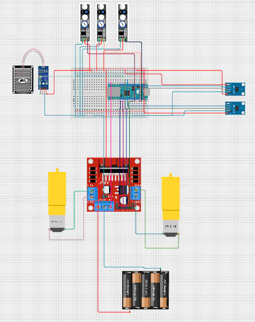
4. Circuit Diagram and Wiring OverviewBefore assembling the full robot, I planned the wiring between the Arduino Nano, L298N motor driver, sensors, and battery pack. The circuit diagram shows how the main modules are connected before they are mounted onto the chassis.
The most important wiring point is that all modules need a common ground. The Arduino Nano, L298N motor driver, rain sensor, line sensors, BH1750 sensors, and battery supply must share ground so that the signals are read correctly.
The main connections used in my final build were:
L298N motor driver:
IN1 → D2
IN2 → D3
IN3 → D4
IN4 → D7

Line sensors:
Left line sensor   → D8
Centre line sensor → D9
Right line sensor  → D10

Rain sensor:
Signal → A0

BH1750 light sensors:
SDA → Arduino SDA
SCL → Arduino SCL
VCC → 3.3V / suitable logic supply
GND → GND

BH1750 addresses:
Left sensor  → 0x23
Right sensor → 0x5C

Power:
6-cell battery pack → L298N motor supply
L298N motor outputs → left and right DC motors
Common GND shared between L298N, Arduino, and sensors
The L298N ENA and ENB jumpers were kept installed, so I did not use PWM pins for speed control. Instead, the final code uses digital pulsed movement to make the motors less aggressive.
5. Building the Chassis
The first step was to assemble the basic robot chassis. I attached the two DC motors, fitted the wheels, and installed the front caster wheel.
At this stage, there were no sensors attached. I only wanted to make sure the robot had a stable base and enough space to mount the breadboard, motor driver, battery pack, and sensors later.
6. Mounting the Breadboard, L298N, and Battery Pack
After the chassis was assembled, I mounted the breadboard, L298N motor driver, and 6-cell battery pack.
I used double-sided tape to attach these parts to the chassis. This made it easier to adjust the component positions while testing. The L298N was mounted close to the motors so the motor wires could reach easily. The breadboard was placed on top so the Arduino and sensor wiring could be added later. The battery pack was mounted so that it could power the robot independently.
At this stage, the robot had the basic parts required for movement:
- battery pack for power;
- L298N for motor control;
- breadboard for wiring;
- Arduino Nano as the controller.
Before adding any sensors, I tested the motor driver and motors using a simple Arduino script.
The purpose of this test was to confirm that:
- the left motor could move forward and backward;
- the right motor could move forward and backward;
- both motors could move together;
- the robot could rotate left and right;
- the stop function worked;
- the battery and L298N could actually power the motors.
This stage was important because motor direction is not always correct on the first attempt. Depending on how the motors are wired, one side may spin in the opposite direction. I adjusted the motor direction settings until the robot could move forward, rotate left, rotate right, and stop correctly.
In my final wiring, the L298N motor control pins were:
IN1 = D2
IN2 = D3
IN3 = D4
IN4 = D7
I kept the L298N ENA/ENB jumpers installed, so the robot did not use PWM pins. Instead, the final code uses digital pulsed movement to make the motors less aggressive.
8. Adding the Line SensorsAfter the motor system worked, I added the three line sensors to the front of the robot.
The three sensors were arranged as:
Left line sensor
Centre line sensor
Right line sensor
I mounted them using a thin malleable metal sheet that I had from one of the breadboards. This worked well because I could bend the metal slightly and position the sensors so they faced downward. I used tape to hold the sensors and bracket in place.
The line sensors were connected to:
Left sensor   = D8
Centre sensor = D9
Right sensor  = D10
At this point, I did not immediately add full line tracking. I first tested the sensors with a simple script that printed the readings. I used black tape only as a testing surface to confirm that the sensors could detect dark and light areas correctly.
The goal of this stage was simply to check that each sensor reacted when it passed over a dark line.
After the line sensors were mounted and tested, I added the rain sensor.
The rain sensor has two main parts:
- the sensing plate;
- the control module.
I mounted the sensing plate where it could be reached easily during testing. The control module was placed near the breadboard. I used double-sided tape again so the sensor position could be adjusted if needed.
The rain sensor output was connected to:
Rain sensor signal = A0I tested the rain sensor separately using a simple script that printed analog readings. I compared the value when the sensor was dry with the value when the sensor was wet. This helped me choose a threshold for detecting rain.
In the final setup, the dry reading was roughly higher and the wet reading was lower, so the final code uses a threshold to decide whether rain is present.
The last sensors I added were the two BH1750 light sensors.
I mounted one BH1750 sensor on the left side of the robot and one on the right side. I used vertical supports so the sensors were raised above the robot body. This gave the sensors a better chance of detecting light from different directions.
Both sensors use I2C, so they needed different addresses:
Left BH1750  = 0x23
Right BH1750 = 0x5C
Before writing the robot rotation logic, I first used a simple test script to confirm that both sensors could take readings. The test printed the left and right lux values so I could check whether each sensor responded when light was pointed toward it.
In the final code, both sensors are initialised like this:
leftLightOK = lightLeft.begin(BH1750::CONTINUOUS_HIGH_RES_MODE, 0x23, &Wire);
rightLightOK = lightRight.begin(BH1750::CONTINUOUS_HIGH_RES_MODE, 0x5C, &Wire);
This allowed the robot to check whether each BH1750 sensor was detected successfully on startup.
After confirming that both BH1750 sensors could take readings, I worked on the sun-balancing logic.
The idea was simple:
If the left sensor sees more light, rotate left.
If the right sensor sees more light, rotate right.
If both readings are close, stop.
The final logic compares the two lux values and uses a deadband so the robot does not rotate for very small differences.
float leftLux = lightLeft.readLightLevel();
float rightLux = lightRight.readLightLevel();

latestLeftLux = leftLux;
latestRightLux = rightLux;

float diff = leftLux - rightLux;

if (diff > -LIGHT_DEADBAND && diff < LIGHT_DEADBAND) {
  sunDirection = 0;
  setEvent("SUN_BALANCED");
  stopMotors();
}

else if (diff > LIGHT_DEADBAND) {
  sunDirection = -1;
  sunRotateUntil = now + SUN_ROTATE_STEP_MS;
  setEvent("SUN_ROTATE_LEFT");
}

else {
  sunDirection = 1;
  sunRotateUntil = now + SUN_ROTATE_STEP_MS;
  setEvent("SUN_ROTATE_RIGHT");
}
The deadband was important because without it the robot could keep rotating even when the light difference was very small. This made the robot more stable.
The sun-tracking behaviour is only used when the robot is in the drying state and laundry active mode is enabled.
12. Developing Movement Using Serial CommandsBefore adding MQTT or the dashboard, I controlled the robot using Serial Monitor commands. This made it easier to test the movement without depending on the backend.
The Serial commands were:
s = go to SAFE
d = go to DRYING
x = stop
The command handling logic looked like this:
void handleSerial() {
  if (!Serial.available()) return;

  char cmd = Serial.read();

  if (cmd == 's' || cmd == 'S') {
    Serial.println("Command: GO_SAFE");
    goToTarget(TARGET_SAFE);
  }

  else if (cmd == 'd' || cmd == 'D') {
    Serial.println("Command: GO_DRYING");
    goToTarget(TARGET_DRYING);
  }

  else if (cmd == 'x' || cmd == 'X') {
    Serial.println("Command: STOP");
    emergencyStop();
  }
}
This stage was useful because I could place the robot on the test surface, send a command, observe the movement, and then adjust the logic.
I adjusted the movement multiple times before reaching a version that worked properly. The robot needed to rotate correctly, search for the line, move forward, and stop when needed.
13. Developing Line Sensor LogicAfter the robot could move using simple Serial commands, I worked on line tracking.
The three line sensors are read as a three-bit pattern:
100 = left sensor detects dark surface
010 = centre sensor detects dark surface
001 = right sensor detects dark surface
111 = all sensors detect dark surface
000 = no sensors detect dark surface
The function below reads the three sensors and converts them into that pattern:
byte readLinePattern() {
  bool leftBlack = digitalRead(LINE_LEFT) == BLACK_DETECTED;
  bool centerBlack = digitalRead(LINE_CENTER) == BLACK_DETECTED;
  bool rightBlack = digitalRead(LINE_RIGHT) == BLACK_DETECTED;

  byte pattern = 0;

  if (leftBlack) pattern |= 0b100;
  if (centerBlack) pattern |= 0b010;
  if (rightBlack) pattern |= 0b001;

  return pattern;
}
This became the base of the robot’s movement logic.
The general movement idea was:
If the centre sensor detects the line, move forward.
If the left sensor detects the line, correct left.
If the right sensor detects the line, correct right.
If no sensor detects the line, search for the line.
If all sensors detect black, treat it as a marker.
The first versions were too sensitive. The robot would sometimes over-correct because it reacted to every small sensor change. I improved this by adding logic that tolerates short flickers and only corrects when needed.
14. Line Hunting and RecoveryOne issue with line following was that the robot could lose the line. When this happened, it needed a way to search for the line again rather than stopping completely.
The final code uses a line-hunting state. When the robot sees the line on the left or right, it locks onto that direction and keeps rotating that way for a short time. This helped reduce random left-right movement.
A simplified explanation of the logic is:
If the line is seen on the right, rotate right.
If the line is seen on the left, rotate left.
If the line is temporarily lost, continue in the last known direction briefly.
If the line is found in the centre, start moving forward.
Part of the line-hunting logic is:
if (pattern == 0b010) {
  state = MOVING;
  markerArmed = false;
  currentlyOnMarker = false;

  huntState = HUNT_SEARCHING;
  huntMissCount = 0;
  lastCorrectionDirection = 0;

  if (target == TARGET_SAFE) {
    setEvent("LINE_CENTERED_MOVING_TO_SAFE");
  } else {
    setEvent("LINE_CENTERED_MOVING_TO_DRYING");
  }

  return;
}

if (pattern == 0b001 || pattern == 0b011) {
  huntState = HUNT_LOCK_RIGHT;
  huntDirection = 1;
  huntMissCount = 0;
  huntLockStartTime = millis();

  setEvent("LOCK_RIGHT_ROTATE_RIGHT");
  rotateRight();
  return;
}

if (pattern == 0b100 || pattern == 0b110) {
  huntState = HUNT_LOCK_LEFT;
  huntDirection = -1;
  huntMissCount = 0;
  huntLockStartTime = millis();

  setEvent("LOCK_LEFT_ROTATE_LEFT");
  rotateLeft();
  return;
}
This was one of the parts that improved the robot’s movement because it stopped the robot from constantly switching direction when the line readings changed quickly.
15. Improving Movement with Forward CommitAnother problem was twitchy movement. If the robot corrected every tiny side reading immediately, it moved too slowly and unevenly.
To reduce this, I used a short forward-commit period. When the robot sees the centre line, it briefly trusts that it is aligned and keeps moving forward. Small flickers are ignored unless they persist.
if (pattern == 0b010) {
  resetForwardCommitCounters();
  lastCorrectionDirection = 0;
  startForwardCommit();
  forward();
  return;
}

if (pattern == 0b100 || pattern == 0b110) {
  sideLeftCount++;
  sideRightCount = 0;
  lastCorrectionDirection = -1;

  if (inForwardCommit() || sideLeftCount < SIDE_CONFIRM_COUNT) {
    setEvent("SIDE_LEFT_DELAY_FORWARD");
    forward();
    return;
  }

  sideLeftCount = 0;
  setEvent("SIDE_LEFT_CONFIRMED_CORRECT");
  strongLeft();
  return;
}

if (pattern == 0b001 || pattern == 0b011) {
  sideRightCount++;
  sideLeftCount = 0;
  lastCorrectionDirection = 1;

  if (inForwardCommit() || sideRightCount < SIDE_CONFIRM_COUNT) {
    setEvent("SIDE_RIGHT_DELAY_FORWARD");
    forward();
    return;
  }

  sideRightCount = 0;
  setEvent("SIDE_RIGHT_CONFIRMED_CORRECT");
  strongRight();
  return;
}
This was an important improvement because it made the robot move more smoothly instead of constantly twitching left and right.
16. Developing Safe Zone and Drying Zone DetectionAfter the robot could follow the line, I added logic for detecting the safe zone and drying zone.
The robot detects zones based on marker patterns. The idea is:
DRYING zone = wide marker followed by centre line
SAFE zone   = wide marker followed by a clear gap and then another wide marker
In terms of sensor patterns:
DRYING = 111 -> 010
SAFE   = 111 -> 000 -> 111
The robot does not trust a single reading. It waits for stable repeated readings before confirming a zone.
if (pattern == 0b000) {
  markerZeroCount++;
  markerCenterCount = 0;
  markerSecondMarkerCount = 0;

  if (!safeGapSeen && markerZeroCount >= SAFE_GAP_CONFIRM_COUNT) {
    safeGapSeen = true;
    setEvent("ZONE_CODE_SAFE_GAP_CONFIRMED");
  } else {
    setEvent("ZONE_CODE_000_CHECKING_SAFE_GAP");
  }

  forward();
  return;
}

if (pattern == 0b010) {
  markerCenterCount++;
  markerZeroCount = 0;

  if (!safeGapSeen && markerCenterCount >= DRYING_CENTER_CONFIRM_COUNT) {
    setEvent("ZONE_CODE_111_010_DRYING_CONFIRMED");
    zoneDecision(ZONE_DRYING);
    return;
  }

  setEvent("ZONE_CODE_010_CHECKING_DRYING");
  forward();
  return;
}

if (pattern == 0b111) {
  markerCenterCount = 0;

  if (safeGapSeen) {
    markerSecondMarkerCount++;

    if (markerSecondMarkerCount >= SAFE_SECOND_MARKER_CONFIRM_COUNT) {
      setEvent("ZONE_CODE_111_000_111_SAFE_CONFIRMED");
      zoneDecision(ZONE_SAFE);
      return;
    }

    setEvent("ZONE_CODE_SECOND_111_CHECKING_SAFE");
    forward();
    return;
  }
}
This logic took several iterations because small errors in sensor readings could cause wrong zone detection. Requiring repeated readings made the system more reliable.
17. Adding Rain BehaviourOnce movement and zone detection were working, I connected the rain sensor logic to the robot behaviour.
The robot should only move to safety if:
Laundry active mode is ON.
The robot is currently in the DRYING state.
The rain sensor reading stays below the threshold long enough.
The rain logic is:
void updateRainSensor() {
  rainRaw = analogRead(RAIN_PIN);
  rainWetNow = rainRaw < RAIN_THRESHOLD;

  if (!laundryActive) {
    rainConfirmed = false;
    rainWetStartTime = 0;
    return;
  }

  if (state != DRYING) {
    if (!rainWetNow) {
      rainConfirmed = false;
      rainWetStartTime = 0;
    }
    return;
  }

  if (rainWetNow) {
    if (rainWetStartTime == 0) {
      rainWetStartTime = millis();
      setEvent("RAIN_DETECTED_WAITING_CONFIRM");
    }

    if (!rainConfirmed && millis() - rainWetStartTime >= RAIN_CONFIRM_MS) {
      rainConfirmed = true;
      setEvent("RAIN_CONFIRMED_GOING_SAFE");
      goToTarget(TARGET_SAFE);
    }
  }

  else {
    if (rainConfirmed) {
      setEvent("RAIN_CLEARED");
    }

    rainConfirmed = false;
    rainWetStartTime = 0;
  }
}
This is one of the most important parts of the project because rain safety is handled locally by the Nano. The dashboard is useful, but the robot does not need to wait for the dashboard to decide that rain is unsafe.
18. Adding MQTT CommunicationAfter the robot worked locally, I added MQTT communication.
MQTT was added so the robot could send telemetry and receive commands remotely. The Nano publishes sensor and state information to a public MQTT broker, and the Raspberry Pi backend subscribes to it.
The MQTT broker is:
const char MQTT_BROKER[] = "broker.hivemq.com";
const int MQTT_PORT = 1883;
The topics are:
const char MQTT_TELEMETRY_TOPIC[] = "smartclothesline/manitkhera26/demo01/telemetry";
const char MQTT_EVENT_TOPIC[]     = "smartclothesline/manitkhera26/demo01/event";
const char MQTT_COMMAND_TOPIC[]   = "smartclothesline/manitkhera26/demo01/command";
const char MQTT_STATUS_TOPIC[]    = "smartclothesline/manitkhera26/demo01/status";
The Nano publishes telemetry as JSON:
StaticJsonDocument<512> doc;

byte pattern = readLinePattern();

doc["device"] = "nano";
doc["state"] = stateName(state);
doc["target"] = targetName(target);
doc["event"] = lastEvent;
doc["line_pattern"] = patternToString(pattern);
doc["rain_raw"] = rainRaw;
doc["rain_status"] = rainStatusName();
doc["left_lux"] = latestLeftLux;
doc["right_lux"] = latestRightLux;
doc["light_left_ok"] = leftLightOK;
doc["light_right_ok"] = rightLightOK;
doc["laundry_active"] = laundryActive;
doc["wifi_ok"] = wifiReady;
doc["mqtt_ok"] = mqttReady;
doc["last_command"] = lastBackendCommand;

char payload[512];
size_t n = serializeJson(doc, payload, sizeof(payload));

mqttClient.publish(MQTT_TELEMETRY_TOPIC, payload, n);
This allows the dashboard to show the robot’s current state, rain status, light readings, line pattern, and latest event.
19. Receiving MQTT CommandsThe robot can also receive MQTT commands from the dashboard.
The supported commands are:
STOP
MOVE_TO_SAFE
RETURN_TO_DRYING
SET_ACTIVE_TRUE
SET_ACTIVE_FALSE
The command handler receives either plain text commands or JSON commands.
void mqttCallback(char* topic, byte* payload, unsigned int length) {
  String message = "";

  for (unsigned int i = 0; i < length; i++) {
    message += (char)payload[i];
  }

  message.trim();

  String command = "";

  StaticJsonDocument<256> doc;
  DeserializationError err = deserializeJson(doc, message);

  if (!err) {
    const char* cmd = doc["command"] | "";
    command = String(cmd);

    const char* source = doc["source"] | "MQTT";
    lastMqttCommandSource = String(source);

    if (doc.containsKey("laundry_active")) {
      laundryActive = doc["laundry_active"] | laundryActive;
    }
  } else {
    command = message;
    lastMqttCommandSource = "MQTT_PLAIN";
  }

  command.trim();
  command.toUpperCase();

  handleMQTTCommand(command);
}
For example, when MOVE_TO_SAFE is received, the robot checks whether it is already in a movement-critical state. If it is not, it starts moving toward the safe zone.
if (command == "MOVE_TO_SAFE") {
  if (isMovementCriticalState()) {
    setEvent("MQTT_CMD_MOVE_SAFE_IGNORED_MOVING");
    publishStatusMessage("CMD_MOVE_SAFE_IGNORED_MOVING");
    return;
  }

  setEvent("MQTT_CMD_MOVE_TO_SAFE");

  delay(200);

  goToTarget(TARGET_SAFE);
  return;
}
This made the robot controllable from the dashboard while still keeping the main safety and movement logic on the Nano.
20. Adding the Raspberry Pi DashboardThe final stage was adding the Raspberry Pi dashboard.
The dashboard was added after the robot itself was working. Its purpose was to make the system easier to monitor and control.
The dashboard shows:
- robot state;
- target zone;
- latest event;
- line sensor pattern;
- rain sensor reading;
- rain status;
- left and right lux readings;
- MQTT status;
- laundry active mode;
- recent logs and events.
It also provides buttons for sending manual commands to the robot, such as moving to the safe zone, returning to the drying zone, stopping the robot, and enabling/disabling laundry active mode.
The Raspberry Pi does not replace the robot’s local logic. The Nano still handles rain response, line tracking, zone detection, movement, and sensor decisions. The dashboard is mainly for monitoring, logging, and remote control.
After confirming that the Flask dashboard worked locally, I moved the backend to a Raspberry Pi.
The first version of the dashboard was tested while the laptop/backend and the Nano were on the same local network. This helped me confirm that the dashboard could send commands and that the Nano could respond correctly. Once that worked, I wanted the backend to run independently instead of depending on my laptop.
The Raspberry Pi was used as a small always-on server for the project. I copied the Flask backend onto the Pi, installed the required Python dependencies, and ran the dashboard from there.
The Raspberry Pi backend was responsible for:
- running the Flask dashboard;
- receiving telemetry from the robot;
- showing robot state and sensor values;
- sending manual commands;
- logging events and status;
- keeping the dashboard available without needing my laptop to run the backend.
This made the Raspberry Pi the main backend and monitoring point for the final system.
22. Making the Flask Backend Run Automatically on BootAfter moving the Flask backend to the Raspberry Pi, I wanted the dashboard to start automatically whenever the Pi booted.
To do this, I configured the Flask backend as a systemd service called:
smart-clothesline.serviceThis meant I did not need to manually run python app.py every time the Raspberry Pi restarted. Instead, Linux could manage the Flask backend like a normal service.
The useful service commands were:
sudo systemctl start smart-clothesline.serviceThis starts the Flask backend.
sudo systemctl stop smart-clothesline.serviceThis stops the backend when I need to make changes.
sudo systemctl restart smart-clothesline.serviceThis restarts the backend after editing files or changing configuration.
sudo systemctl status smart-clothesline.serviceThis checks whether the backend is running correctly.
journalctl -u smart-clothesline.service -fThis shows the live backend logs. I used this to debug Flask errors, MQTT issues, and command problems.
sudo systemctl enable smart-clothesline.serviceThis enables the service to start automatically when the Raspberry Pi boots.
sudo systemctl disable smart-clothesline.serviceThis disables automatic startup if I no longer want the backend to run on boot.
This setup made the project more reliable because the Raspberry Pi could be restarted and the dashboard would come back online automatically.
23. Adding Remote Dashboard Access with TailscaleOnce the backend was running properly on the Raspberry Pi, I wanted to access the dashboard remotely from my laptop.
To do this, I used Tailscale. I connected both my Raspberry Pi and my laptop to the same Tailscale network. This allowed my laptop to reach the Raspberry Pi using the Pi’s Tailscale IP address, even when I was not on the same local Wi-Fi network.
The important point is that Tailscale was used for remote dashboard access, not for direct Nano communication.
The final remote architecture was:
Laptop browser
      ↓
Tailscale network
      ↓
Raspberry Pi Flask dashboard
      ↓
MQTT broker
      ↓
Nano 33 IoT robot
So from my laptop, I could open the Raspberry Pi dashboard remotely using a URL like:
http://<raspberry-pi-tailscale-ip>:5000/The dashboard running on the Pi then communicated with the Nano 33 IoT through MQTT. This meant I could access the dashboard remotely, and the dashboard could still send commands to the robot and receive telemetry from it.
This made the project closer to a real IoT system because the user does not need to be physically connected to the robot or the Raspberry Pi’s local network.
24. Testing the Dashboard on the Raspberry Pi and TailscaleAfter setting up the Raspberry Pi service and Tailscale, I tested the dashboard again.
The testing process was:
- Start or restart the Flask backend service on the Raspberry Pi.
- Check the service status using
systemctl status. - Open the dashboard from my laptop using the Raspberry Pi’s Tailscale IP address.
- Confirm that the dashboard loaded correctly.
- Confirm that the backend was connected to MQTT.
- Confirm that Nano telemetry appeared on the dashboard.
- Send commands from the dashboard.
- Check that the Nano 33 IoT received the commands and responded.
- Use
journalctllogs if something did not work.
This confirmed that the system was no longer just a local laptop-based test. The backend was running on a dedicated Raspberry Pi, the dashboard could be accessed remotely through Tailscale, and the robot could still communicate with the backend using MQTT.
The dashboard became the main remote interface for the system. It displayed the robot’s state, rain readings, light sensor values, line sensor pattern, MQTT status, latest event, and command controls.
The Raspberry Pi and Tailscale setup made the project much more practical.
The Raspberry Pi acted as a dedicated backend server, so I did not need to keep the Flask app running on my laptop. Tailscale allowed my laptop to access the Raspberry Pi dashboard remotely. MQTT allowed the Raspberry Pi backend and Nano 33 IoT robot to communicate even when they were not directly connected through the same local network.
This separated the system into clear roles:
Nano 33 IoT = sensors, motor control, rain response, line tracking
MQTT broker = communication between robot and backend
Raspberry Pi = Flask backend, dashboard, logging, command publishing
Tailscale = remote access to the Raspberry Pi dashboard
Laptop = user interface through the browser
This separation made the project easier to manage and closer to a real smart clothesline system. The Nano focused on controlling the robot, the Raspberry Pi handled the dashboard/backend, and Tailscale made the dashboard accessible remotely.
26. Final Demonstration and ResultsThe final robot successfully demonstrates the main behaviour of the smart clothesline concept. When laundry active mode is enabled, the robot can stay in the drying area, monitor the rain sensor, compare light readings from the two BH1750 sensors, and communicate live status information to the Raspberry Pi dashboard through MQTT.When rain is detected and confirmed, the Arduino Nano 33 IoT handles the safety response locally. The robot follows the line track, identifies the correct zone markers, and moves from the drying area to the safe area without needing the dashboard to make the decision. The dashboard can still be used to monitor the robot state, view sensor readings, and send manual commands such as moving to the safe zone, returning to the drying zone, stopping the robot, or enabling/disabling laundry active mode.A demonstration of the completed system can be viewed here:
This article is part of an assignment submitted to Deakin University, School of IT, Unit SIT210/730 - Embedded Systems Development.


_3u05Tpwasz.png?auto=compress%2Cformat&w=40&h=40&fit=fillmax&bg=fff&dpr=2)
Comments