
Hardware components | ||||||
| × | 1 | ||||
| × | 1 | ||||
| × | 2 | ||||
 |
| × | 1 | |||
| × | 1 | ||||
| × | 1 | ||||
Software apps and online services | ||||||
 |
| |||||
| ||||||
In this project, I planned to get a much better understanding of how to implement different sensors as well as getting experience with path planning. I have been working on most of this since the beginning of the semester and I am happy to have a working result.
Autonomous robotics is growing every year and it is only a matter of time until we see autonomy everywhere! Tesla's cars are a great example of simple autonomy as they can path plan, map an environment, and make decisions with ease but are not quite reliable or moral enough for complete autonomy dealing with human life and uncertainty. In controlled environments like an automated warehouse, these complex decisions are nonexistent and autonomy can be fully adventured.
In this project, I will be using a LIDAR as the primary means for obstacle detection. A* will be used for precise node-based path planning and the Optitrack Motive software for motion-capture-based dead reckoning.
Results at the bottom if you would just like to see just the final project.
What Is Path Planning?How do you get from one place to another? Well, you could just walk randomly until you get to your destination or you could PLAN. Planning a path allows for an optimal or functional path to be laid out that will start at one point and end at another. Think about solving a maze. Sure you could just follow the left or right wall until you reached the end but there is both a chance this will take a LONG time and certainly a chance for you to loop forever if there is no way to the exit. A path plan allows you to know whether there is a way to your desired position as well as a more direct path there.
There are many different types of path planning algorithms, some examples include Dijkstra's, A*, and Breadth First Search. This project will focus on the A* algorithm for path planning as it is the most direct form for a single endpoint out of the three mentioned above.
- Breadth First Search will search every direction at the same time for the shortest path. This is a very useful algorithm but is not ideal for path planning.
- Dijkstra's Algorithm is used instead of Breadth as it favors the lowest cost path. Nodes or paths that get you closer to your end goal are prioritized.
- The A* Algorithm is a modification and optimized version of Dikstra's for one endpoint.
A LIDAR simply is just a sensor for distance measurements. A laser is shot out of the LIDAR and the time it takes to get back determines the distance from the sensor. Many 2D LIDARs including the one I have in this project will give you many points and distances around the entire sensor, like the image above.
Above is an example of what a LIDAR can do.
Motion Capture?Simply, I do not need to use the motion capture as I could use the measurements from the motor to dead reckon the robot car; however, the mechatronics room has the motion capture system set up. This makes the robot car's position very easy to locate; therefore, making precise movements simple to perform. I will be connecting an Orange PI, a cheap Raspberry PI, to the motion capture software's network and retrieve the data. This will then send the data to the microcontroller.
Robot Car Motor ControlTo start up the coding portion of this project I will go over the code for controlling the DC motors
// Read the motor rotation
    RightWheel = readEncRight();
    LeftWheel = -readEncLeft();

    // distance ft
    XLeftK = 1/(radftL/LeftWheel);
    XRightK = 1/(radftR/RightWheel);
    // vel ft/s
    VLeftK = (XLeftK - XLeftK1)/0.004;
    VRightK = (XRightK - XRightK1)/0.004;
The code below reads the corresponding motor's rotation angle and with the known radius of the wheel, I can calculate the distance traveled and velocity of the wheel.
float readEncLeft(void) {
    int32_t raw = 0;
    uint32_t QEP_maxvalue = 0xFFFFFFFFU; //4294967295U
    raw = EQep1Regs.QPOSCNT;
    if (raw >= QEP_maxvalue/2) raw -= QEP_maxvalue; // I don't think this is needed an           d never true
    // 5 North South magnet poles in the encoder disk so 5 square waves per one revolution of the
    // DC motor's back shaft. Then Quadrature Decoder mode multiplies this by 4 so 20 counts per one rev
    // of the DC motor's back shaft. Then the gear motor's gear ratio is 30:1.
    return (raw*(1/(20*30/(2*PI))));
}
Once the velocity and distance are calculated every 1ms, I implemented a PI controller to smoothly control the motors with a decided Vref and Turn.
// PI

    eturn = turn + (VLeftK - VRightK);

    ekLeft = Vref - VLeftK - (Kturn*eturn);
    IkLeft = IkLeft1 + 0.004*((ekLeft + ekLeft1)/2);
    uLeft = (Kp*ekLeft) + (Ki*IkLeft);

    ekRight = Vref - VRightK + (Kturn*eturn);
    IkRight = IkRight1 + 0.004*((ekRight + ekRight1)/2);
    uRight = (Kp+ekRight) + (Ki*IkRight);
After the PI controller calculations, I simply set the motors to the decided uLeft and uRight values. I must also saturate uLeft and uRight in case of integral wind up with is a common problem with PID control. I make sure to same the current states to the past states.
//integral wind up
    if(fabs(uLeft) >= 10) {
        IkLeft = IkLeft1;
    }
    if(fabs(uRight) >= 10){
        IkRight = IkRight1;
    }


    setEPWM2A(uRight);
    setEPWM2B(-uLeft);

    //states
    XLeftK1 = XLeftK;
    XRightK1 = XRightK;
    IkLeft1 = IkLeft;
    IkRight1 = IkRight;
    ekLeft1 = ekLeft;
ekRight1 = ekRight;To use the LIDAR we had to find out what data we were getting from the sensor and how to organize it. The data is sent from the LIDAR to the microcontroller over SPIRXD. The code written for communicating with the LIDAR uses states to check and read the initializations and data from the sensor.
The data from the LIDAR is sent in packets all starting with the packet header 0xAA. This is what we check for first and if 0x55AA is found we can move on to state 2, if not we keep looking for it.
if(state == 0) { //check 0xaa
        if(data == 0xAA) {
            state = 1;
        } else {
            state = 0;
        }
} else if (state == 1) {//check 0x55
        if(data == 0x55) {
            state = 2;
        } else {
            state = 0;
        }
Next, we check to see whether the packet sent is the start packet or the point cloud packet, 0x00. If it is the point cloud packet we advance.
} else if (state == 2) {//check 0x0
        if (data == 0x0) {
            state = 3;
//            packetcount+=1;
        } else {
            state = 0;
        }
We then read the number of samples in the packet and we record it.
} else if (state == 3){ //read sample size
        sampleSize = data;
        state = 4;
}
Next, is to read and record both the start and end angles.
} else if (state == 4) {//read starting angle lsb
        startangleLSB = data;
        state = 5;
    } else if (state == 5) {//record starting angle
            start_angle = ((((data<<8)| startangleLSB)>>1)&0x7FFF)/64.0;
        state = 6;
    } else if (state == 6) { //read end angle
            endLSB = data;
        state = 7;
    } else if (state == 7) {//record end angle
        end_angle = ((((data<<8)| endLSB)>>1)&0x7FFF)/64.0;

        if (end_angle < start_angle) {
            cor_end = end_angle + 360;
        } else {
            cor_end = end_angle;
        }
        delta_angle = cor_end-start_angle;
        state = 8;
}
Lastly, we can record the LIDAR data points and tell the microcontroller to ignore the checks since we will assume it will stay the same as long as the LIDAR is running. We make sure to use a ping-pong buffer to make sure we have enough time to record the data and do not miss any.
} else if (state == 8) {//record samples and ignore the check code
        if(position > 1) {
            if (dis_state == 0){
                dLSB = data;
                dis_state = 1;
            } else if (dis_state == 1){

                    float raw_angle = (delta_angle)/(sampleSize - 1) * (sampleindex) +start_angle;
                    sampleindex = sampleindex+1;
                    if(sampleindex == sampleSize) {
                        sampleindex = 0;
                    }
                    pts[arrayIndex].rawAngle = raw_angle;
                    if(dist == 0){
                        cal_angle = raw_angle;
                    } else {
                        cal_angle = raw_angle + atan(21.8*(155.3-dist)/(155.3*dist))*57.296;
                    }
                    pts[arrayIndex].cor_angle = cal_angle;

                    if (pingpongflag == 1) {
                        pingpts[((int16_t)(cal_angle + 0.5))%360].distance = dist;
                        pingpts[((int16_t)(cal_angle + 0.5))%360].timestamp = numTimer0calls;
                    } else {
                        pongpts[((int16_t)(cal_angle + 0.5))%360].distance = dist;
                        pongpts[((int16_t)(cal_angle + 0.5))%360].timestamp = numTimer0calls;
                    }
                    dis_count += 1;
                    dis_state = 0;
                    if (arrayIndex < 599) {
                        arrayIndex += 1;
                    }
            }
        }
NOW WE HAVE DATA! We also make sure to take the data and organize it into a nice structure that tells up the angle, distance, and timestamp. I also included the custom 3D part that I created for my robot.
The A* AlgorithmSince we have the LIDAR working it's time to get the A* algorithm working for path planing the robot. As stated before A* is a modified version of Dijkstra's algorithm.
The A* and Dijkstra algorithms both use a Priority Queue to prioritize paths with a lower or higher cost. Priority Queues are not the same as a normal queue would be on a first-in-first-out basis while a Priority Queue organizes its queue by "highest priority", lowest cost. For more information about the code behind a priority queue please visit the link below.
http://pages.cs.wisc.edu/~vernon/cs367/notes/11.PRIORITY-Q.html
The easiest way to explain the A* algorithm is that it takes both the actual distance from the start and estimates the distance to the goal.
f=g+h
The equation above is the basis of A* as F is the totalcost of the node, G is the distance between the current node and the start node, and H is the heuristicdistance, estimated distance from the current node to the end node. The full A* algorithm function can be found in my source code below I will share the Pseudocode that helped me create the algorithm for my map.
// A*
Function A*(start,goal)

// Initialize the closed list, the set of nodes already evaluated Closedset = the empty set
//Initialize the open list, the set of tentative nodes to be evaluated //initially containing the start node
Start g score = 0 Start
f score = g score plus h “Manhattan distance from start to goal”
Openset = {start} came_from = empty
// The map of the navigated nodes
while the open list is not empty
    Find the node with the least f on the open list, call it "q"
    Pop q off the open list
    Generate q's 4 neighbors
    For each neighbor  If neighbor is the goal, stop the search
        neighbor.g = q.g + distance between neighbor and q
        // h distance is the “Manhattan” distance on a square grid
        neighbor.h = distance from goal to neighbor
        neighbor.f = neighbor.g + neighbor.h

        If a node with the same position as neighbor is in the OPEN list \  which has a lower f than neighbor, skip adding this neighbor

        if a node with the same position as neighbor is in the CLOSED list \  which has a lower f than neighbor, skip adding this neighbor

        otherwise, add the node to the open list and came_from[neighbor] = q //set neighbor’s parent equal to q
    end
    push q on the closed list
endAfter completing my A* code I can now set a map to any size I want, I chose 16X11 as that is the size of the grid I will be driving in.
int startRow = 4;
int startCol = 5;
int endRow = 15;
int endCol = 1;
char mapCourseStart[176] =      //16x11
{   '0', '0', '0', '0', '0', '0', '0', '0', '0', '0', '0',
    '0', '0', '0', '0', '0', '0', '0', '0', '0', '0', '0',
    '0', '0', '0', '0', '0', '0', '0', '0', '0', '0', '0',
    '0', '0', '0', '0', '0', '0', '0', '0', '0', '0', '0',
    'x', 'x', 'x', 'x', '0', '0', '0', 'x', 'x', 'x', 'x',    //start row
    '0', '0', '0', '0', '0', '0', '0', '0', '0', '0', '0',
    '0', '0', '0', '0', '0', '0', '0', '0', '0', '0', '0',
    '0', '0', '0', '0', '0', '0', '0', '0', '0', '0', '0',
    '0', '0', '0', '0', '0', '0', '0', '0', '0', '0', '0',
    '0', '0', '0', '0', '0', '0', '0', '0', '0', '0', '0',
    '0', '0', '0', '0', '0', '0', '0', '0', '0', '0', '0',
    '0', '0', '0', '0', '0', '0', '0', '0', '0', '0', '0',
    '0', '0', '0', '0', '0', '0', '0', '0', '0', '0', '0',
    '0', '0', '0', '0', '0', '0', '0', '0', '0', '0', '0',
    '0', '0', '0', '0', '0', '0', '0', '0', '0', '0', '0',
    '0', '0', '0', '0', '0', '0', '0', '0', '0', '0', '0'   };

if (PathFunction == 1){ // 1 for A* path
            // create the map
            mapRowSize = 16;
            mapColSize = 11;
            //reset Search flag
            obsSearch = 0;
            if(astarC == 0){   //Starting position
                startRow = 4;
                startCol = 5;
            }else{
                //floor the astar start point
                startRow = floorf(ROBOTps.y);
                startCol = floorf(ROBOTps.x);
            }
            astarC++;
            int i = 0;
            for(i = 0; i<mapRowSize*mapColSize; i++){        //copy m1 into map for solving
                map[i] = mapCourseStart[i];
            }
The code above creates a 16X11 map and sets a start Row and start Column as well as copies a predetermined map with no obstacles that will be updated as they are added.
astar(startRow,startCol,endRow,endCol); // solve pathWe then run the A* function with a specified endpoint. This should result in a path. After a few more checks to make sure the start and endpoints are in bounds and that they are not on an obstacle. The A* function can return 1 of 3 values 1, 2, or 3.
retvalue = astar(startRow,startCol,endRow,endCol);
                    if (retvalue == 1) {
                        serial_printf(&SerialA,"   pathLength %d\r\n", pathLen);
                        int i = 0;
                        for(i = 0; i< pathLen; i++)     //put solution on map
                        {
                            int mapIdx = pathRow[i]*mapColSize + pathCol[i];
                            map[mapIdx] = '-';
                        }
                        //put path nodes into structure node_path
                        int p = 0;
                        for(p = 0; p < pathLen; p++)
                        {
                            path[p].row = pathRow[(pathLen-1)-p];
                            path[p].col = pathCol[(pathLen-1)-p];
                        }

                        //print map with solution
                        i = 0;
                        int j = 0;
                        for(i=0; i<mapRowSize; i++)
                        {
                            for(j = 0; j<mapColSize; j++)
                            serial_printf(&SerialA,"   %c  ", map[i*mapColSize+j]);
                            serial_printf(&SerialA,"\r\n");
                        }
If it returns a 1, WE HAVE A PATH! We then take this path and add it to the solution map and print the solution. This path starts from the end and goes to the start so I made sure to make a path array that turns this around for easier use in the future.
If the function returns a 2 it is already at this point and we print an ERROR.
} else if (retvalue == 2) {
                        serial_printf(&SerialA,"\r\n");
                        serial_printf(&SerialA,"\r\n");
                        serial_printf(&SerialA,"\r\n");
                        serial_printf(&SerialA,"\r\n");
                        serial_printf(&SerialA,"!!!!!!!!!!!!!!!!Error!!!!!!!!!!!!!!!\r\n");
                        serial_printf(&SerialA,"Already at this point.  No Astar needed.\r\n");
                        serial_printf(&SerialA,"!!!!!!!!!!!!!!!!Error!!!!!!!!!!!!!!!\r\n");
                        serial_printf(&SerialA,"\r\n");
                        serial_printf(&SerialA,"\r\n");
                        serial_printf(&SerialA,"\r\n");
                        serial_printf(&SerialA,"\r\n");
The function will return a 3 if a valid path is not found for the robot.
} else {
                        serial_printf(&SerialA,"\r\n");
                        serial_printf(&SerialA,"\r\n");
                        serial_printf(&SerialA,"\r\n");
                        serial_printf(&SerialA,"\r\n");
                        serial_printf(&SerialA,"!!!!!!!!!!!!!!!!Error!!!!!!!!!!!!!!!\r\n");
                        serial_printf(&SerialA,"No Path Found Obstacle in the path.\r\n");
                        serial_printf(&SerialA,"!!!!!!!!!!!!!!!!Error!!!!!!!!!!!!!!!\r\n");
                        serial_printf(&SerialA,"\r\n");
                        serial_printf(&SerialA,"\r\n");
                        serial_printf(&SerialA,"\r\n");
                        serial_printf(&SerialA,"\r\n");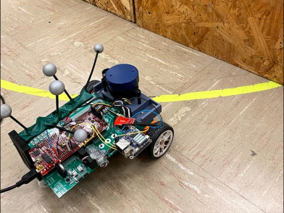
}We have a path for our robot and we can run the wheels but how are we going to get the robot to smoothly follow the track? First, we make sure we know where our robot car is at all times. The OptiTrack Motive software allows me to strap some reflective balls to the top of my robot car with a 3D print I printed and it will track the center of those balls. I can then use that as the center of my robot car so I precisely know where it is at all times in the grid.
We read the data coming to use over SPIRXC with the code below.
void serialRXC(serial_t *s, char data) {

    if (newData == 0) {
        pastRecChar[0] = data;
        if ( (pastRecChar[0] == ':') &&
             (pastRecChar[1] == 'i') &&
             (pastRecChar[2] == 't') &&
             (pastRecChar[3] == 'p') &&
             (pastRecChar[4] == 'O')
           ) {
            newData = 1;
            numRXC = 0;
            pastRecChar[0] = 0;
            pastRecChar[1] = 0;
            pastRecChar[2] = 0;
            pastRecChar[3] = 0;
            pastRecChar[4] = 0;
        }
        pastRecChar[4] = pastRecChar[3];
        pastRecChar[3] = pastRecChar[2];
        pastRecChar[2] = pastRecChar[1];
        pastRecChar[1] = pastRecChar[0];


    } else if (newData == 1) {
        if ((numRXC % 2) == 0) {
            OptiRecv.rawdata[numRXC/2] = data & 0xFF;
        } else {
            OptiRecv.rawdata[numRXC/2] = ((data << 8) & 0xFF00) | OptiRecv.rawdata[numRXC/2];
        }
        numRXC++;
        if (numRXC >= 20) {
            numRXC = 0;
            newData = 0;
            Opti_x = OptiRecv.data[0];
            Opti_y = OptiRecv.data[1];
            Opti_theta = OptiRecv.data[2];
            Opti_Body = OptiRecv.data[3];
            Opti_Stamp = OptiRecv.data[4];
//            x = cpu2tocpu1[0];
//            y = cpu2tocpu1[1];
//            theta = cpu2tocpu1[2];
//            number = cpu2tocpu1[3];
//            framecount = cpu2tocpu1[4];
            OPTITRACKps = UpdateOptitrackStates(ROBOTps);
            ROBOTps.x = OPTITRACKps.x +5  ; //adding 5 to make grids match
            ROBOTps.y = OPTITRACKps.y +4 ;  //adding 11 to make grids match
            ROBOTps.theta = OPTITRACKps.theta;
            UARTPrint = 1;
        }
    }


}
First, we have to make sure the data that is sent to us is correct. When checking the starting characters make sure "OPTI:" is sent. If it is then copy the data and save it to the Opti variables. I had to make my grid and the OptiTrack grid match by adding 5 to the "x" and 4 to the "y".
Now we know where our robot is! I then made a function xy_control that will take a current x, y, and theta position, and a desired x and y position. This function will then continuously output the necessary Vref and Turn values to get to your position.
int xy_control(float *vref_forxy, float *turn_forxy,float turn_thres, float x_pos,float y_pos,float x_desired,float y_desired,
                float thetaabs,float target_radius,float target_radius_near)
{

        // calculate theta (current heading) between -PI and PI
    if (thetaabs > PI) {
        theta = thetaabs - 2.0*PI*floorf((thetaabs+PI)/(2.0*PI));
    } else if (thetaabs < -PI) {
        theta = thetaabs - 2.0*PI*ceilf((thetaabs-PI)/(2.0*PI));
    } else {
        theta = thetaabs;
    }

    dx = x_desired - x_pos;
    dy = y_desired - y_pos;
    dist = sqrtf( (dx*dx) + (dy*dy) );
    dir = 1.0;
Here we can see the start of the function and the calculation of the distance to the target.
// calculate alpha (trajectory angle) between -PI and PI
    alpha = my_atanf(dy,dx);

    // calculate turn error
    //  turnerror = theta - alpha;  old way using left hand coordinate system.
    turnerror = alpha - theta;
We then create an error to minimize as we turn. This error is the difference between the trajectory angle and the current angle.
if (dist < target_radius_near) {
        target_near = 1;
        // Arrived to the target's (X,Y)
        if (dist < target_radius) {
            dir = 0.0;
            turnerror = 0.0;
        } else {
            // if we overshot target, we must change direction. This can cause the robot to bounce back and forth when
            // remaining at a point.
            if (fabsf(turnerror) > HALFPI) {
                dir = -dir;
            }
            turnerror = 0;
        }
    } else {
        target_near = 0;
    }
Then we can check to see if we have reached our target. We should do this before setting Vref and Turn. If the robot gets within the specified distance of the target, target_radius, we can say that they have reached the target and stop. If we overshoot the target we will turn around and go back.
// vref is 1 tile/sec; but slower when close to target.
    *vref_forxy = dir*min(dist+0.1,1);

    if (fabsf(*vref_forxy) > 0.0) {
        // if robot 1 tile away from target use a scaled KP value.
        *turn_forxy = (*vref_forxy*2)*turnerror;
    } else {
        // normally use a Kp gain of 2
        *turn_forxy = 2*turnerror;
    }

    // This helps with unbalanced wheel slipping.  If turn value greater than
    // turn_thres then just spin in place
    if (fabsf(*turn_forxy) > turn_thres) {
        *vref_forxy = 0;
    }
    return(target_near);
If we are not at our target we update Vref and Turn with a proportional controller. Now we can run the A* algorithm and follow the path!
See the A* youtube video below.
Obstacle DetectionNow here comes the hard part. How does the robot know there is something in its way and how can we plan around that? What I did was I gave the robot some rules. "Obstacles can only be at these places and if you see something around that area is an obstacle at that spot". Sounds easy enough, right? I went along and made rules for 48 edges that could be obstacles.
obs[46].x = 5; //ROBOTps
    obs[46].y = 6;
    obs[46].tally = 0;
    obs[46].found = 0;
    obs[46].idx1 = 72;
    obs[46].idx2 = 71;
    obs[46].idx3 = 70;
    obs[47].x = 3; //ROBOTps
    obs[47].y = 6;
    obs[47].tally = 0;
    obs[47].found = 0;
    obs[47].idx1 = 70;
    obs[47].idx2 = 69;
    obs[47].idx3 = 68;
    obs[48].x = 1; //ROBOTps
    obs[48].y = 6;
    obs[48].tally = 0;
    obs[48].found = 0;
    obs[48].idx1 = 68;
    obs[48].idx2 = 67;
obs[48].idx3 = 66;I then made sure to find the center of each obstacle and their corresponding indexes for the Course Map. If an obstacle was found I tallied it up. If it reached 4 or more tallies I changed those "0" in the map to an "X" and then ran A* again and got a new path.
To do this I first had to know the distance at which my LIDAR reading was Globally. Since the LIDAR and OptiTrack system had different bases I had to make sure they were the same, with the code below.
if (UseLIDARping == 1) {
            UseLIDARping = 0;
            int i = 0;
            // change of basis
            for (i = 0; i < 360; i++) {
                //if the data is not available, set all of them to 0 to avoid messing things up
                if (pingpts[i].distance ==0) {
                    x_f[i].distance = 0;
                    y_f[i].distance = 0;
                    x_f[i].timestamp = pingpts[i].timestamp;
                    y_f[i].timestamp = pingpts[i].timestamp;
                } else {
                    x_ori[i] = pingpts[i].distance*cos(i*0.01745329)/304;//0.017453292519943 is pi/180
                    y_ori[i] = pingpts[i].distance*sin(i*0.01745329)/304;
                    x_f[i].distance = (x_ori[i])*sin(ROBOTps.theta)+(y_ori[i])*cos(ROBOTps.theta)+(ROBOTps.x); //change basis
                    y_f[i].distance = (x_ori[i])*cos(ROBOTps.theta)+(y_ori[i])*sin(ROBOTps.theta)+(ROBOTps.y); //change basis
//                    x_f[i].distance = (x_ori[i]+pose_x)*cos(pose_rad)-(y_ori[i]+pose_y)*sin(pose_rad); //change basis
//                    y_f[i].distance = (x_ori[i]+pose_x)*sin(pose_rad)+(y_ori[i]+pose_y)*cos(pose_rad); //change basis
                }
            }
            if (PathFunction == 2){
                searchObs();
            }
This was also a great time to search and see if I had obstacles. To search for obstacles I had to FOR loop over every obstacle and see if the difference between the LIDAR reading and their corresponding x and y positions were under 0.35 ft.
void searchObs(){
    int i = 0;
    for(i = 0; i < 49; i++){
        // search lidar angles
//        }
        if(x_ori[90] < 1.5 && x_ori[90] > 0){
            if(y_ori[90] < 1.5 && y_ori[90] > 0){
                obsDisx = (x_f[90].distance - obs[i].x);
                obsDisy = (y_f[90].distance - obs[i].y);
                obsDist = sqrtf((obsDisx*obsDisx)*(obsDisy*obsDisy));
                if(obsDist < 0.35){
                    obs[i].tally++;
                }
            }
        }
I did this for 4 more angles, 45, 135, 170, and 10 degrees. If the tallies reached 4 they were officially an obstacle and marked found. The function then gives a flag, obsSearch, that there was a found obstacle which tells the robot to STOP and find a new path.
if(obs[i].tally > 3){
            if (obs[i].found == 0){
                mapCourseStart[obs[i].idx1] = 'x';
                mapCourseStart[obs[i].idx2] = 'x';
                mapCourseStart[obs[i].idx3] = 'x';
                //Flag that an obs has been found
                obsSearch = 1;
                obs[i].found = 1;
            }
        }
Putting it all together! First I made a "PathFunction" flag that will tell the robot what state it is in. It could be "1" which is A*, "2" which is follow the path and look for obstacles, or "3" which is STANDBYE. The robot is started by a button.
void ReadSwitches(void) {
    if(GpioDataRegs.GPADAT.bit.GPIO4 == 0){
        PathFunction = 1;
    }
    if(GpioDataRegs.GPADAT.bit.GPIO5 == 0){
        PathFunction = 2;
    }
    if(GpioDataRegs.GPADAT.bit.GPIO6 == 0){
        PathFunction = 0;
    }
    if(GpioDataRegs.GPADAT.bit.GPIO7 == 0){
        PathFunction = 3;
    }
}
To start press the button to run A* this will give a path to the endpoint on a blank map and will push "PathFunction" to 2.
if(PathFunction == 2){ // DRIVE THE PATH AFTER A*  !!USE Lidar and obstacle indentification to interrupt PATHFUCTION = 2
        //Run xycontrol for first path node changing desired x and y after each iteration until PathLen amount of times.
        //This should end at the end of the path !!MUST WATCH FOR SLIPPING OF WHEELS!!
        if(target_near == 1){
            nodenumber++; //progress in path
            target_near = 0;
        }
        //A*
        if(obsSearch == 1){
            if(astarC < 50){
                PathFunction = 1;
                nodenumber = 0;
            }
//            PathFunction = 1;
//            nodenumber = 0;
        }
Once "PathFunction = 2" we then first check to see if we are near a target. If we are we say to progress in the path. If not we check to see if we found an obstacle before moving on in the path. If we found one, obsSearch = 1, we go back to A*. If not we are free to go to the desired node.
x_desired = (path[nodenumber+1].col);
        y_desired = (path[nodenumber+1].row);
        x_pos = ROBOTps.x;
        y_pos = ROBOTps.y;
        thetaabs = ROBOTps.theta;
        xy_control(&vref_forxy, &turn_forxy,turn_thres,x_pos,y_pos,x_desired,y_desired,
                   thetaabs,target_radius,target_radius_near);
        Vref = vref_forxy;
        turn = turn_forxy;
        if(nodenumber == pathLen-1){  //end of path!
            PathFunction = 3;
            Vref = 0;
            turn = 0;
        }
We calculate the desired x and y and update our robot's position using the motion capture. We then run xy_control to update Vref and Turn. Lastly, we check to see if we reached the end of our path. If so, we sit in STANDBYE until further instruction.
Project Results!Before I get into the results I would like to say that I had a great time doing this project and I learned more about robotics in this project than anything before. If you find this interesting please try it out.
A* Path Planning Results!The A* results came back fantastic as the robot was zooming around the track precisely dodging every obstacle I manually put on the map.
Above is the result of the A* path planning, xy_control, and motion capture combination of the project. The robot easily follows the path given to it and dodges obstacles with ease.
Obstacle Detection Results!Obstacle detection was by far the hardest part of this project. The robot car was able to reliably see and map obstacles when standing still but had some trouble when turning and moving.
Above is one of the successful runs of the autonomous robot car. As you can see path 1 and path 4 are completely different and the robot saw all obstacles it needed to see. Below is the video showing a successful run finding two obstacles and planning around them.
Here you can see the robot clearly spot the two obstacles and change its course to go around them. The robot ended up making it to its desired location without hitting the obstacles put in its way. Compare this to the video below of the robot detecting one of the two obstacles wrong.
Above you can see the robot try to A* away then find a phantom obstacle and run into the other obstacle.
Overall this project was a GREAT SUCCESS! This can obviously be tuned and improved, but the theory and code of the project make a real-life autonomous robot.
Thank YouI could not have done this without the help of Professor Dan Block for not only supplying the materials but also helping in any way he could! Thanks, Dan!
I hope you enjoyed my project and learned something along the way. Thank you for your time!


Comments