

Hardware components | ||||||
 |
| × | 1 | |||
 |
| × | 1 | |||
Software apps and online services | ||||||
| ||||||
| ||||||
 |
| |||||
Create an account in NXP Studio and develop your firmware for your NXP Rapid IOT Prototyping device.
You can make your own firmware by dragging the elements in the IDE or you can also use my firmware which I advise (included in the files section down below). Click 'Import project' then upload the project file (*.atmo).
A detailed description of the components can be found by clicking the component itself then click the question mark icon in the upper left which will be redirected to the atmosphere documentation. Full list of the atmosphere documentation can be found here.
- Set Interval - will trigger any connected elements for 5 seconds.
- Backlight - this can be set to low, medium, high or off but in this particular scenario we want it to be turned off to save some battery.
- Sensors - I used all of the sensors available with the device except for the Accelerometer and the Gyrocsope
- BLE-GATT - This element will send the data from the device to the raspberry pi through BLE. Remember to write down the characteristic UUIDS for every BLE-GATT.
- Custom Functions (Charging State and BatteryLevel )- if you can notice on the elements toolbox, getting the battery info, like the battery level and the charging state of the device, is not included. Luckily, there is an available Rapid IOT SDK Reference Manual which can be downloaded here.
According to the manual in Chapter 4: Battery sensor, we can get the current battery state by using this function.
In the NXP Rapid Studio, click the element function. Then click the code view which we can write some custom functions that fits our needs.
Add this code to get the Charging State of the device.
ATMO_Status_t Charging_State_trigger(ATMO_Value_t *in, ATMO_Value_t *out) {
	uint8_t batteryPercentLevel = 0;
	uint8_t batteryChargingState = 0;
	BatterySensor_GetState(&batteryPercentLevel, &batteryChargingState);
	ATMO_CreateValueUnsignedInt(out, batteryChargingState);
	return ATMO_Status_Success;
}
Then also add another function and paste this code to get the Battery Percent level of the device.
ATMO_Status_t Battery_Level_trigger(ATMO_Value_t *in, ATMO_Value_t *out) {
	uint8_t batteryPercentLevel = 0;
	uint8_t batteryChargingState = 0;
	BatterySensor_GetState(&batteryPercentLevel, &batteryChargingState);
	ATMO_CreateValueUnsignedInt(out, batteryPercentLevel);
	return ATMO_Status_Success;
}
Before loading your own custom firmware, make sure you saved your project. Then click the compile button which is located in the upper right part of the IDE. If everything is fine, a notification will prompt the the compilation is successful. Click the download button which will then download the firmware of the device (*.bin).
In uploading the firmware to the device, follow the instructions which can be found here on how to upload the firmware to the device. All of the instructions that I said from compilation, downloading the firmware up until uploading it in the device is discussed in that document. (Page 133 - 134)
Go to https://io.adafruit.com/ and create an account.
Why Chose Adafruit IO?
It is free, easy to use and it can be easily integrated with IFTTT (If this then that) which we will be discussed later.
Just like any free platforms, there are also some limitations in using this platform.
In the free plan, we are limited to 30 data points per minute, 30 data storage, 10 feeds and 5 dashboards per account.
Terminologies:
- Feeds - Feeds contain the sensor data that we are sending from the device. For more info ( https://learn.adafruit.com/adafruit-io-basics-feeds)
- Dashboard - Dashboards allow you to visualize data and control Adafruit IO connected projects. For more info (https://learn.adafruit.com/adafruit-io-basics-dashboards)
We will be creating 8 feeds which correspond to:
- Ambient Light
- Battery Level
- Charging Status
- Co2 Level
- Humidity
- Pressure
- Temperature
- TVOC
Just like what I have stated earlier that in free plan, we can only create 10 Feeds (Maximum). So if you are planning to modify this and send some other data, you should take this into consideration.
NOTE: After Creating all feeds, please do take note of the Key column in the feeds table as we will be needing this in getting the value of that specific feed later.
Another significant feature of adafruit.io is that you can download a feed data in CSV Format. Just go to the Feeds => Click the specific feed you want to download and down below there is a button to download all the data (Reminder: Storage is only for 30 Days for Free Plan)
Create a dashboard that will be the home for all of your feeds. Click Action > Create a New Dashboard and fill up the necessary data like the name of your dashboard.
Next, click the dashboard that you have created.
Now, let's create some blocks in the dashboard. Blocks are widgets that we can add base on the value from a feed. Click the plus icon in the upper right.
A detailed explanation on what is the function of each specific blocks can be found in the documentation of adafruit here.
For this example we will be using Gauge for our temperature levels.
Fill up the necessary information like the Block Title, Minimum and Maximum value of the Gauge. Set some low and high warning value as well then click create Block.
Repeat these steps again depending on the number of feeds you want to use. You can add a line graph, a reset button and many more, depending on your needs.
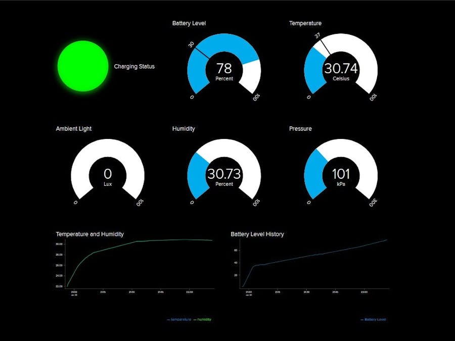
This is what my dashboard looks like
(Note: As you can see there is no TVOC and CO2 gauge. It is because for some reason the device that they sent to me is defective and can’t measure gas levels.)
Step 7: Get Your Unique AIO KeyWe will be needing your AIO Key later in getting the data from your Adafruit IO to our python code. Make sure not to share your AIO Key to others because they can access the data from your account.
You can view your AIO Key from your dashboard by click the key icon. Copy your username and AIO Key and save it somewhere safe as of now.
For this project, I am using Python version 3. Out of the box, Python 3 is already installed. So we are good to go.
Open the folder Python Code, open your favorite terminal then install the following packages.
pip3 install pygatt
This is for Pygatt - a python module for Bluetooth LE Generic Attribute Profile (GATT). Documentation can be found here.
pip3 install adafruit-io
adafruit-io - is a python library and examples for use with io.adafruit.com. Documentation can also be found here.
Step 9: Python CodeThe full code is included down below. In this step we will be taking a look at the code in detail.
import unicodedata
import time
import pygatt
import Adafruit_IO
Unicode data is a built in package in python which we will be using to convert the bytearray into string coming from the NXP Device to the Raspberry Pi. And time for the delay, we will be discussing it later on why we need this.
BLE_ADDRESS = '--:--:--:--:--:--'
Your Bluetooth address is located at the back of the NXP Device. You can follow the format down below
SENSOR_UUIDS = {
"temperature": "09c0c6b0-f14c-4e4f-b94a-d3aefbfd4668",
"humidity" :"09c0c6b0-f14c-4e4f-b94a-d3aefbfd4669",
"air_quality_tvoc":"09c0c6b0-f14c-4e4f-b94a-d3aefbfd466a",
"air_quality_co2": "09c0c6b0-f14c-4e4f-b94a-d3aefbfd466b",
"pressure": "09c0c6b0-f14c-4e4f-b94a-d3aefbfd466c",
"ambient-light": "09c0c6b0-f14c-4e4f-b94a-d3aefbfd466d"  ,
"battery-level": "09c0c6b0-f14c-4e4f-b94a-d3aefbfd4666",
"charging-status": "09c0c6b0-f14c-4e4f-b94a-d3aefbfd4667"
}
Remember about the characteristic UUIDS in NXP Rapid Online IDE? This is where we put the UUIDS in order for us to get the sensor data.
ADAFRUIT_IO_USERNAME = "***************************"
ADAFRUIT_IO_KEY = "********************************"
aio = Client(ADAFRUIT_IO_USERNAME, ADAFRUIT_IO_KEY)
Adafruit.io Configuration. Your username and your AIO Key
temp = aio.feeds('temperature')
humid = aio.feeds('humidity')
pressure = aio.feeds('pressure')
bat_status = aio.feeds('charging-status')
bat_level = aio.feeds('battery-level')
light = aio.feeds('ambient-light')
tvoc = aio.feeds('tvoc')
co2 = aio.feeds('co2')
The key value of your feeds. With the format aio.feeds("FEED_NAME_KEY_VALUE")
time.sleep(10)
You may ask. What is the delay for? Recall that for the free plan of Adafruit.IO we can only make 60 requests within 60 second or 1 request for 1 second. In our app we are sending 8 requests in total. That's why we need to delay every request every 10 seconds so that we won't reach the limit.
After all of the configuration. You can run the code by using the command in your terminal from the directory where the file is located.
python app.py
If everything works fine you can go to your Adafruit IO Dashboard and view as each values change :)
Step 10: Connecting to IFTTTIFTTT (If this then that) is a free web based app that let us connect devices and make some conditions without writing a single code.
First is you have to create an account in https://ifttt.com. You can use the web app or download the app in the playstore. For this tutorial, I will be using the web app.
At first it can be really overwhelming. But I will try to guide you in connecting the adafruit.io to IFTTT.
Second, Go to https://ifttt.com/services and search for Adafruit and Click Connect. You will be redirected to the Adafruit Page and you have to make sure that the account signed in is the one that you use in your project then click Authorize.
That's It! You have now successfully connected Adafruit IO to IFTTT.
Step 11: Creating an Applet for Our ProjectAn Applet connects two or more apps or devices together. It enables you to do something that those apps or devices couldn't do on their own.
Click the My Applets in the Upper Left > Click New Applet to Create one.
Click this button then search for the service that we enabled last time which is the adafruit.io
Think of triggers as events on your service. Some example triggers are “Any new post” or “New photo added to album” or “Any new motion.”
For this specific project we are monitoring a feed on our Adafruit IO.
Automatically our Feeds can be found in the Feed Drop-down menu and we can choose on how we trigger this event. Let's say for example
If the temperature is greater than 37 then "I will do something later on".
Click Create Trigger
Next we create the Then Part and this is where IFTTT really shines. There are a lot of services available you can use. If you have a smart light, a smart Air Purifier, smart Air Conditioner, a smart Plug or any Internet Connected device that is available in IFTTT, you can use it here.
I don't have any smart devices here so for now I will choose the sms service available. I want to receive a text message whenever the temperature exceeds 37 Degrees Celsius.
Note: In order for this service to work, you have to download the App in your phones.
Congratulations! You have now created your first applet in IFTTT! Your challenge now would be to create other applets! Create an applet if the value of the Co2 Level would be greater at that specific level, you turn on your Philipps Hue Smart Light Red! Just imagine the possibilities on what you can make! Enjoy!


Comments