


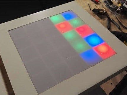
A simple side table with high-gloss lacquer is the basis for our modification. Such tables, which are already available for under 10 $, usually consist only of a thin MDF (pressboard) on the top and bottom, in the middle of a honeycomb pattern made of cardboard provides the necessary stability. Thus, the table can also be edited with a sharp pocket or kitchen knife, special wooden tool is not necessary.Cut a hole, about 40cmx40cm in the table (see picture). Later, a diffuse Plexiglas pane will be used as a substitute for the tabletop. If possible, this should be the same color as the table. Press the cardboard in at the side a little so that the Arduino can be placed later.The LED table uses 25 LEDs in different colors (green, red, blue). So that you get beautiful lighting effects later and the LEDs do not overlap each other, a wooden frame is built. The components of the wooden frame are made of plywood boards (4mm).
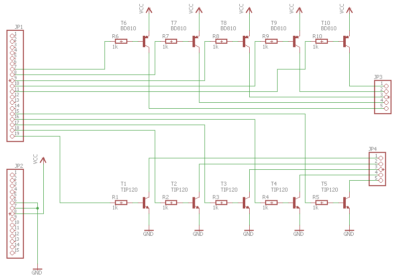
The 25 individual LEDs are jointly controlled by an Arduino Uno (SMD version).Since the power of the Arduino is not sufficient to drive the LEDs directly, we have designed a small board that can be piggybacked on the Arduino. So you can use the table quickly, but at the same time also use for other projects.The board consists of ten power transistors, each controlling one of the five plus and minus poles. So we can address each individual LED by means of PWM and cascading without having to connect 25 LEDs directly to the Arduino.The Arduino can now switch with its low power the transistors, which in turn give power to the LEDs.The board in this post has been etched. Optionally, you can etch the board yourself (starter sets are available to buy) or on the Internet the board for little money to etch according to your desire. The advantage of this is that you can put the board as a plug-and-play solution on the Arduino. The layout for the board can be found in the info box. Of course, the board can also be copied on a breadboard, for which we have provided the wiring diagram for you.
From the plywood saw 8 frames (4 with openings upwards, 4 with openings downwards). The drawing can be found in the info box. Put the frames together crosswise and glue the wooden frame.Each LED has its own chamber. The wooden frame is a stable connection that increases the load capacity of the table top. The size of the wooden frame is the size of the Plexiglas plate.
Wire the LED to a network. As a template for sawing off the cables, the wooden grid is used. All positive poles lead to one side, all negative poles to the other. The harnesses are routed together on the Arduino.For LEDs different resistors have to be selected. The pre-resistance depends on the operating voltage and the color of the LEDs. On the supply line (positive poles) the protective resistor is being attached.We create the light effects with the Arduino. There are no limits to the imagination, everything you like is feasible. From simple figures to dynamically changing patterns you can realize everything. With Pulse Width Modulation (PWM), several LEDs may appear lit at the same time, although in reality the Arduino only turns the individual LEDs on and off a few hundred times per second. Following the same principle, the LEDs are also dimmed in brightness.
On the additional board (piggyback board) power transistors are mounted. These switch the actual power to the LED network because the Arduino is unable to do so. A total of 10 power transistors are mounted on the board. A corresponding circuit diagram can be found in the info box.
When the Arduino is programmed and the board is soldered, we can start assembling. First, the LEDs are wired, the grid serves as a template for cutting to length of the cable. The finished cable network should look like a network: All positive poles lead to one side, all negative poles to the other. These grids we put now in the table and fix the LEDs with hot glue. Then the grid can also be inserted and glued, in wood, preferably with a wood glue. When the glue is dry, we hide in the left edge of the table nor the Arduino and make it accessible via a small hole from the outside to the power supply, then we glue the Plexiglas pane.


Comments