


Hardware components | ||||||
 |
| × | 1 | |||
 |
| × | 1 | |||
 |
| × | 4 | |||
Software apps and online services | ||||||
 |
| |||||
Hand tools and fabrication machines | ||||||
 |
| |||||
 |
| |||||
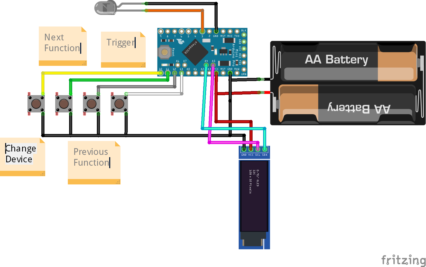
I wanted to make a universal remote that was more interesting than just some box with buttons on it. My idea was to take a Nerf blaster and replace the mechanisms inside with a circuit that would work as an IR remote. While looking for a blaster I stumbled upon a home laser tag toy that uses IR already. Since it already had a battery holder, electronic trigger, and built in IR LED it was perfect. I made this video to talk about it and show off how it works!

/*
 *  PinDefinitionsAndMore.h
 *
 *  Contains pin definitions for IRremote examples for various platforms
 *  as well as definitions for feedback LED and tone() and includes
 *
 *  Copyright (C) 2021-2022  Armin Joachimsmeyer
 *  armin.joachimsmeyer@gmail.com
 *
 *  This file is part of IRremote https://github.com/Arduino-IRremote/Arduino-IRremote.
 *
 *  Arduino-IRremote is free software: you can redistribute it and/or modify
 *  it under the terms of the GNU General Public License as published by
 *  the Free Software Foundation, either version 3 of the License, or
 *  (at your option) any later version.
 *
 *  This program is distributed in the hope that it will be useful,
 *  but WITHOUT ANY WARRANTY; without even the implied warranty of
 *  MERCHANTABILITY or FITNESS FOR A PARTICULAR PURPOSE.
 *  See the GNU General Public License for more details.
 *
 *  You should have received a copy of the GNU General Public License
 *  along with this program. If not, see <http://www.gnu.org/licenses/gpl.html>.
 *
 */

/*
 * Pin mapping table for different platforms
 *
 * Platform     IR input    IR output   Tone      Core/Pin schema
 * --------------------------------------------------------------
 * DEFAULT/AVR  2           3           4         Arduino
 * ATtinyX5     0|PB0       4|PB4       3|PB3     ATTinyCore
 * ATtiny167    3|PA3       2|PA2       7|PA7     ATTinyCore
 * ATtiny167    9|PA3       8|PA2       5|PA7     Digispark pro
 * ATtiny3217  18|PA1      19|PA2      20|PA3     MegaTinyCore
 * ATtiny1604   2           3|PA5       %
 * ATtiny816   14|PA1      16|PA3       1|PA5     MegaTinyCore
 * ATtiny1614   8|PA1      10|PA3       1|PA5     MegaTinyCore
 * SAMD21       3           4           5
 * ESP8266      14|D5       12|D6       %
 * ESP32        15          4           27
 * BluePill     PA6         PA7         PA3
 * APOLLO3      11          12          5
 * RP2040       3|GPIO15    4|GPIO16    5|GPIO17
 */
//#define _IR_MEASURE_TIMING // For debugging purposes.

#if defined(__AVR__)
#if defined(__AVR_ATtiny25__) || defined(__AVR_ATtiny45__) || defined(__AVR_ATtiny85__) // Digispark board
#include "ATtinySerialOut.hpp" // TX is at pin 2 - Available as Arduino library "ATtinySerialOut". Saves 700 bytes program memory and 70 bytes RAM for ATtinyCore
#define IR_RECEIVE_PIN  0
#define IR_SEND_PIN     4 // Pin 2 is serial output with ATtinySerialOut. Pin 1 is internal LED and Pin3 is USB+ with pullup on Digispark board.
#define TONE_PIN        3
#define _IR_TIMING_TEST_PIN 3

#  elif defined(__AVR_ATtiny87__) || defined(__AVR_ATtiny167__) // Digispark pro board
#include "ATtinySerialOut.hpp" // Available as Arduino library "ATtinySerialOut"
// For ATtiny167 Pins PB6 and PA3 are usable as interrupt source.
#  if defined(ARDUINO_AVR_DIGISPARKPRO)
#define IR_RECEIVE_PIN   9 // PA3 - on Digispark board labeled as pin 9
//#define IR_RECEIVE_PIN  14 // PB6 / INT0 is connected to USB+ on DigisparkPro boards
#define IR_SEND_PIN      8 // PA2 - on Digispark board labeled as pin 8
#define TONE_PIN         5 // PA7 - on Digispark board labeled as pin 5
#define _IR_TIMING_TEST_PIN 10 // PA4
#  else
#define IR_RECEIVE_PIN  3 // PA3 - on Digispark board labeled as pin 9
#define IR_SEND_PIN     2 // PA2 - on Digispark board labeled as pin 8
#define TONE_PIN        7 // PA7 - on Digispark board labeled as pin 5
#  endif

#  elif defined(__AVR_ATtiny88__) // MH-ET Tiny88 board
#include "ATtinySerialOut.hpp" // Available as Arduino library "ATtinySerialOut". Saves 128 bytes program memory
// Pin 6 is TX pin 7 is RX
#define IR_RECEIVE_PIN   3 // INT1
#define IR_SEND_PIN      4
#define TONE_PIN         9
#define _IR_TIMING_TEST_PIN 8

#  elif defined(__AVR_ATtiny1616__)  || defined(__AVR_ATtiny3216__) || defined(__AVR_ATtiny3217__) // Tiny Core Dev board
#define IR_RECEIVE_PIN  18
#define IR_SEND_PIN     19
#define TONE_PIN        20
#define APPLICATION_PIN  0 // PA4
#undef LED_BUILTIN         // No LED available on the TinyCore 32 board, take the one on the programming board which is connected to the DAC output
#define LED_BUILTIN      2 // PA6

#  elif defined(__AVR_ATtiny816__) // Tiny Core Micro
#define IR_RECEIVE_PIN  14 // PA1
#define IR_SEND_PIN     16 // PA3
#define TONE_PIN         1 // PA5
#define APPLICATION_PIN  0 // PA4
#undef LED_BUILTIN         // No LED available, take the one which is connected to the DAC output
#define LED_BUILTIN      4 // PB5

#  elif defined(__AVR_ATtiny1614__)
#define IR_RECEIVE_PIN   8 // PA1
#define IR_SEND_PIN     10 // PA3
#define TONE_PIN         1 // PA5
#define APPLICATION_PIN  0 // PA4

#  elif defined(__AVR_ATtiny1604__)
#define IR_RECEIVE_PIN   2 // To be compatible with interrupt example, pin 2 is chosen here.
#define IR_SEND_PIN      3
#define APPLICATION_PIN  5

#define tone(...) void()      // Define as void, since TCB0_INT_vect is also used by tone()
#define noTone(a) void()
#define TONE_PIN        42 // Dummy for examples using it

#  elif defined(__AVR_ATmega1284__) || defined(__AVR_ATmega1284P__) \
|| defined(__AVR_ATmega644__) || defined(__AVR_ATmega644P__) \
|| defined(__AVR_ATmega324P__) || defined(__AVR_ATmega324A__) \
|| defined(__AVR_ATmega324PA__) || defined(__AVR_ATmega164A__) \
|| defined(__AVR_ATmega164P__) || defined(__AVR_ATmega32__) \
|| defined(__AVR_ATmega16__) || defined(__AVR_ATmega8535__) \
|| defined(__AVR_ATmega64__) || defined(__AVR_ATmega128__) \
|| defined(__AVR_ATmega1281__) || defined(__AVR_ATmega2561__) \
|| defined(__AVR_ATmega8515__) || defined(__AVR_ATmega162__)
#define IR_RECEIVE_PIN      2
#define IR_SEND_PIN        13
#define TONE_PIN            4
#define APPLICATION_PIN     5
#define ALTERNATIVE_IR_FEEDBACK_LED_PIN 6 // E.g. used for examples which use LED_BUILDIN for example output.
#define _IR_TIMING_TEST_PIN 7

#  else // Default as for ATmega328 like on Uno, Nano, Leonardo, Teensy 2.0 etc.
#define IR_RECEIVE_PIN      2 // To be compatible with interrupt example, pin 2 is chosen here.
#define IR_SEND_PIN         3
#define TONE_PIN            4
#define APPLICATION_PIN     5
#define ALTERNATIVE_IR_FEEDBACK_LED_PIN 6 // E.g. used for examples which use LED_BUILDIN for example output.
#define _IR_TIMING_TEST_PIN 7

#    if defined(ARDUINO_AVR_PROMICRO) // Sparkfun Pro Micro is __AVR_ATmega32U4__ but has different external circuit
// We have no built in LED at pin 13 -> reuse RX LED
#undef LED_BUILTIN
#define LED_BUILTIN         LED_BUILTIN_RX
#    endif
#  endif // defined(__AVR_ATtiny25__)...

#elif defined(ESP8266)
#define FEEDBACK_LED_IS_ACTIVE_LOW // The LED on my board (D4) is active LOW
#define IR_RECEIVE_PIN          14 // D5
#define IR_SEND_PIN             12 // D6 - D4/pin 2 is internal LED
#define _IR_TIMING_TEST_PIN      2 // D4
#define APPLICATION_PIN         13 // D7

#define tone(...) void()      // tone() inhibits receive timer
#define noTone(a) void()
#define TONE_PIN                42 // Dummy for examples using it

#elif defined(CONFIG_IDF_TARGET_ESP32C3)
#define IR_INPUT_PIN             8
#define IR_SEND_PIN              9
#define TONE_PIN                10 // ADC2_0
#define APPLICATION_PIN         11

#elif defined(ESP32)
#include <Arduino.h>

// tone() is included in ESP32 core since 2.0.2
#if !defined(ESP_ARDUINO_VERSION_VAL)
#define ESP_ARDUINO_VERSION_VAL(major, minor, patch) 12345678
#endif
#if ESP_ARDUINO_VERSION  <= ESP_ARDUINO_VERSION_VAL(2, 0, 2)
#define TONE_LEDC_CHANNEL        1  // Using channel 1 makes tone() independent of receiving timer -> No need to stop receiving timer.
void tone(uint8_t aPinNumber, unsigned int aFrequency){
    ledcAttachPin(aPinNumber, TONE_LEDC_CHANNEL);
    ledcWriteTone(TONE_LEDC_CHANNEL, aFrequency);
}
void tone(uint8_t aPinNumber, unsigned int aFrequency, unsigned long aDuration){
    ledcAttachPin(aPinNumber, TONE_LEDC_CHANNEL);
    ledcWriteTone(TONE_LEDC_CHANNEL, aFrequency);
    delay(aDuration);
    ledcWriteTone(TONE_LEDC_CHANNEL, 0);
}
void noTone(uint8_t aPinNumber){
    ledcWriteTone(TONE_LEDC_CHANNEL, 0);
}
#endif // ESP_ARDUINO_VERSION  <= ESP_ARDUINO_VERSION_VAL(2, 0, 2)

#define IR_RECEIVE_PIN          15  // D15
#define IR_SEND_PIN              4  // D4
#define TONE_PIN                27  // D27 25 & 26 are DAC0 and 1
#define APPLICATION_PIN         16  // RX2 pin

#elif defined(ARDUINO_ARCH_STM32) || defined(ARDUINO_ARCH_STM32F1) // BluePill
// Timer 3 blocks PA6, PA7, PB0, PB1 for use by Servo or tone()
#define IR_RECEIVE_PIN          PA6
#define IR_RECEIVE_PIN_STRING   "PA6"
#define IR_SEND_PIN             PA7
#define IR_SEND_PIN_STRING      "PA7"
#define TONE_PIN                PA3
#define _IR_TIMING_TEST_PIN     PA5
#define APPLICATION_PIN         PA2
#define APPLICATION_PIN_STRING  "PA2"
#  if defined(ARDUINO_GENERIC_STM32F103C) || defined(ARDUINO_BLUEPILL_F103C8)
// BluePill LED is active low
#define FEEDBACK_LED_IS_ACTIVE_LOW
#  endif

#elif defined(ARDUINO_ARCH_APOLLO3) // Sparkfun Apollo boards
#define IR_RECEIVE_PIN  11
#define IR_SEND_PIN     12
#define TONE_PIN         5

#elif defined(ARDUINO_ARCH_MBED) && defined(ARDUINO_ARCH_MBED_NANO) // Arduino Nano 33 BLE
#define IR_RECEIVE_PIN      3   // GPIO15 Start with pin 3 since pin 2|GPIO25 is connected to LED on Pi pico
#define IR_SEND_PIN         4   // GPIO16
#define TONE_PIN            5
#define APPLICATION_PIN     6
#define ALTERNATIVE_IR_FEEDBACK_LED_PIN 7 // E.g. used for examples which use LED_BUILDIN for example output.
#define _IR_TIMING_TEST_PIN 8

#elif defined(ARDUINO_ARCH_RP2040) // Arduino Nano Connect, Pi Pico with arduino-pico core https://github.com/earlephilhower/arduino-pico
#define IR_RECEIVE_PIN      15  // GPIO15 to be compatible with the Arduino Nano RP2040 Connect (pin3)
#define IR_SEND_PIN         16  // GPIO16
#define TONE_PIN            17
#define APPLICATION_PIN     18
#define ALTERNATIVE_IR_FEEDBACK_LED_PIN 19 // E.g. used for examples which use LED_BUILDIN for example output.
#define _IR_TIMING_TEST_PIN 20

// If you program the Nano RP2040 Connect with this core, then you must redefine LED_BUILTIN
// and use the external reset with 1 kOhm to ground to enter UF2 mode
#undef LED_BUILTIN
#define LED_BUILTIN          6

#elif defined(PARTICLE) // !!!UNTESTED!!!
#define IR_RECEIVE_PIN      A4
#define IR_SEND_PIN         A5 // Particle supports multiple pins

#define LED_BUILTIN         D7

/*
 * 4 times the same (default) layout for easy adaption in the future
 */
#elif defined(TEENSYDUINO) // Teensy 2.0 is handled at default for ATmega328 like on Uno, Nano, Leonardo etc.
#define IR_RECEIVE_PIN      2
#define IR_SEND_PIN         3
#define TONE_PIN            4
#define APPLICATION_PIN     5
#define ALTERNATIVE_IR_FEEDBACK_LED_PIN 6 // E.g. used for examples which use LED_BUILDIN for example output.
#define _IR_TIMING_TEST_PIN 7

#elif defined(ARDUINO_ARCH_MBED) // Arduino Nano 33 BLE
#define IR_RECEIVE_PIN      2
#define IR_SEND_PIN         3
#define TONE_PIN            4
#define APPLICATION_PIN     5
#define ALTERNATIVE_IR_FEEDBACK_LED_PIN 6 // E.g. used for examples which use LED_BUILDIN for example output.
#define _IR_TIMING_TEST_PIN 7

#elif defined(ARDUINO_ARCH_SAMD) || defined(ARDUINO_ARCH_SAM)
#define IR_RECEIVE_PIN      2
#define IR_SEND_PIN         3
#define TONE_PIN            4
#define APPLICATION_PIN     5
#define ALTERNATIVE_IR_FEEDBACK_LED_PIN 6 // E.g. used for examples which use LED_BUILDIN for example output.
#define _IR_TIMING_TEST_PIN 7

#if !defined(ARDUINO_SAMD_ADAFRUIT)
// On the Zero and others we switch explicitly to SerialUSB
#define Serial SerialUSB
#endif

// Definitions for the Chinese SAMD21 M0-Mini clone, which has no led connected to D13/PA17.
// Attention!!! D2 and D4 are swapped on these boards!!!
// If you connect the LED, it is on pin 24/PB11. In this case activate the next two lines.
//#undef LED_BUILTIN
//#define LED_BUILTIN 24 // PB11
// As an alternative you can choose pin 25, it is the RX-LED pin (PB03), but active low.In this case activate the next 3 lines.
//#undef LED_BUILTIN
//#define LED_BUILTIN 25 // PB03
//#define FEEDBACK_LED_IS_ACTIVE_LOW // The RX LED on the M0-Mini is active LOW

#elif defined (NRF51) // BBC micro:bit
#define IR_RECEIVE_PIN      2
#define IR_SEND_PIN         3
#define APPLICATION_PIN     1
#define _IR_TIMING_TEST_PIN 4

#define tone(...) void()    // no tone() available
#define noTone(a) void()
#define TONE_PIN           42 // Dummy for examples using it

#else
#warning Board / CPU is not detected using pre-processor symbols -> using default values, which may not fit. Please extend PinDefinitionsAndMore.h.
// Default valued for unidentified boards
#define IR_RECEIVE_PIN      2
#define IR_SEND_PIN         3
#define TONE_PIN            4
#define APPLICATION_PIN     5
#define ALTERNATIVE_IR_FEEDBACK_LED_PIN 6 // E.g. used for examples which use LED_BUILDIN for example output.
#define _IR_TIMING_TEST_PIN 7
#endif // defined(ESP8266)

#if defined(ESP32) || defined(ARDUINO_ARCH_RP2040) || defined(PARTICLE) || defined(ARDUINO_ARCH_MBED)
#define SEND_PWM_BY_TIMER // We do not have pin restrictions for this CPU's, so lets use the hardware PWM for send carrier signal generation
#else
# if defined(SEND_PWM_BY_TIMER)
#undef IR_SEND_PIN // SendPin is determined by timer! This avoids warning in IRTimer.hpp
#  endif
#endif

#if !defined (FLASHEND)
#define FLASHEND 0xFFFF // Dummy value for platforms where FLASHEND is not defined
#endif
#if !defined (RAMEND)
#define RAMEND 0xFFFF // Dummy value for platforms where RAMEND is not defined
#endif
#if !defined (RAMSIZE)
#define RAMSIZE 0xFFFF // Dummy value for platforms where RAMSIZE is not defined
#endif

/*
 * Helper macro for getting a macro definition as string
 */
#if !defined(STR_HELPER)
#define STR_HELPER(x) #x
#define STR(x) STR_HELPER(x)
#endif
//Needed to run ssd1306 display
#include <SPI.h>
#include <Wire.h>
#include <Adafruit_GFX.h>
#include <Adafruit_SSD1306.h>

#define SCREEN_WIDTH 128 // OLED display width, in pixels
#define SCREEN_HEIGHT 32 // OLED display height, in pixels

// Declaration for an SSD1306 display connected to I2C (SDA, SCL pins)
// The pins for I2C are defined by the Wire-library.
// On an arduino UNO:       A4(SDA), A5(SCL)
// On an arduino MEGA 2560: 20(SDA), 21(SCL)
// On an arduino LEONARDO:   2(SDA),  3(SCL), ...
#define OLED_RESET     -1 // Reset pin # (or -1 if sharing Arduino reset pin)
#define SCREEN_ADDRESS 0x3C ///< See datasheet for Address; 0x3D for 128x64, 0x3C for 128x32
Adafruit_SSD1306 display(SCREEN_WIDTH, SCREEN_HEIGHT, &Wire, OLED_RESET);

#include <Arduino.h>

//Needed for IR Library
#define DISABLE_CODE_FOR_RECEIVER // Disables restarting receiver after each send. Saves 450 bytes program memory and 269 bytes RAM if receiving functions are not used.

#include "PinDefinitionsAndMore.h" // Define macros for input and output pin etc. IR_SEND_PIN is set here to pin 3
#include <IRremote.hpp>

//Pin defs for input and outputs
#define DEVICE_SELECT_PIN 10
#define NEXT_FUNCTION_PIN 11
#define PREV_FUNCTION_PIN 12
#define FUNC_ACTIVATE_PIN 13

bool buttonStates[] = {1,1,1,1};
int debounceDelay = 50;
unsigned long debounceTimes[] = {0,0,0,0};
int buttonPins[] = {
        DEVICE_SELECT_PIN,
        NEXT_FUNCTION_PIN,
        PREV_FUNCTION_PIN,
        FUNC_ACTIVATE_PIN
    };


#define MOTOR_ACTIVATE_PIN 9

struct function
{
    const char * name;
    int numCommands;
    uint8_t* commands;
};

class Device {
    public:
        int numFunctions;
        int currSelected;
        String name;
        function* functions;
        uint16_t deviceId;

        Device(String deviceName, uint16_t Id){
            name = deviceName;
            deviceId = Id;
            numFunctions = 0;
            currSelected = 0;
            functions = (function*)malloc(sizeof(function));
        }

        void addFunction(const char* funcName, uint8_t cmd1){
            functions = (function*)realloc(functions,sizeof(function)*(numFunctions+1));
            function* newFunc = &functions[numFunctions];
            // newFunc->name = (char *)malloc(sizeof(char)*100);
            newFunc->name = funcName;
            newFunc->numCommands = 1;
            newFunc->commands = (uint8_t*)malloc(sizeof(uint8_t));
            newFunc->commands[0] = cmd1;
            numFunctions += 1;
        }

        void addFunction(const char* funcName, uint8_t cmd1, uint8_t cmd2){
            functions = (function*)realloc(functions,sizeof(function)*(numFunctions+1));
            function* newFunc = &functions[numFunctions];
            // newFunc->name = (char *)malloc(sizeof(char)*100);
            newFunc->name = funcName;
            newFunc->numCommands = 2;
            newFunc->commands = (uint8_t*)malloc(sizeof(uint8_t)*2);
            newFunc->commands[0] = cmd1;
            newFunc->commands[1] = cmd2;
            numFunctions += 1;
        }

        void addFunction(const char* funcName, uint8_t cmd1, uint8_t cmd2,uint8_t cmd3){
            functions = (function*)realloc(functions,sizeof(function)*(numFunctions+1));
            function* newFunc = &functions[numFunctions];
            // newFunc->name = (char *)malloc(sizeof(char)*100);
            newFunc->name = funcName;
            newFunc->numCommands = 3;
            newFunc->commands = (uint8_t*)malloc(sizeof(uint8_t)*3);
            newFunc->commands[0] = cmd1;
            newFunc->commands[1] = cmd2;
            newFunc->commands[2] = cmd2;
            numFunctions += 1;
        }

        function* addFunctionGetPointer(){
            functions = (function*)realloc(functions,sizeof(function)*(numFunctions+1));
            numFunctions++;
            return &functions[numFunctions-1];
        }

        function* getCurrentFunction(){
            return &functions[currSelected];
        }

        function* getNextFunction(){
            currSelected = (currSelected + 1) % numFunctions;
            return &functions[currSelected];
        }

        function* getPrevFunction(){
            currSelected = (currSelected - 1);
            if(currSelected < 0)
                currSelected = numFunctions - 1;
            return &functions[currSelected];
        }
};

Device TV("Tv Remote",0xc7ea);
Device Fan("Fan Remote",0x7f80);
Device Humidifier("Humidifier Remote",0x7f80);
Device AtTinyReciever("ATTiny Reciever",0x7f80)
Device* deviceList[] = {&TV,&Fan,&Humidifier,&AtTinyReciever};
int numDevices = 4;
int currDevice = 0;
void setup() {
    Serial.begin(115200);

    // SSD1306_SWITCHCAPVCC = generate display voltage from 3.3V internally
    if(!display.begin(SSD1306_SWITCHCAPVCC, SCREEN_ADDRESS)) {
        Serial.println(F("SSD1306 allocation failed"));
        for(;;); // Don't proceed, loop forever
    }

    display.clearDisplay();
    display.setTextSize(1);             // Normal 1:1 pixel scale
    display.setTextColor(SSD1306_WHITE);        // Draw white text
    display.setCursor(0,0);             // Start at top-left corner
    display.println(F("Make it 4 Less"));
    display.setRotation(2);
    display.display();

    for(int i = 0 ; i < 4; i++){
        pinMode(buttonPins[i],INPUT_PULLUP);
    }

    pinMode(MOTOR_ACTIVATE_PIN,OUTPUT);

    TV.addFunction("Power",0x17,0x97);
    TV.addFunction("Confirm",0x2A,0x7A);
    TV.addFunction("Play/Pause",0x4C,0xCC);
    TV.addFunction("Mute",0x20,0xA0);
    TV.addFunction("Volume up",0x0F,0x8F);
    TV.addFunction("Volume Down",0x10,0x90);

    Fan.addFunction("Power",0x1B);
    Fan.addFunction("Speed",0x1E);
    Fan.addFunction("Rotate",0x12);

    Humidifier.addFunction("Power",0x1A);
    Humidifier.addFunction("Percent",0x04);
    Humidifier.addFunction("Speed",0x06);
    Humidifier.addFunction("UV",0x1F);
    Humidifier.addFunction("Sleep",0x0f);
    Humidifier.addFunction("Timer",0x0A);

    AtTinyReciever.addFunction("Activate",0xFC)

    /*
     * The IR library setup. That's all!
     */
    IrSender.begin(DISABLE_LED_FEEDBACK); // Start with IR_SEND_PIN as send pin and disable feedback LED at default feedback LED pin
}

void loop() {
    /*
     * Print current send values
     */

     for(int i = 0; i < 4; i ++){
            int reading = digitalRead(buttonPins[i]);
            if( reading != buttonStates[i]){
                if(millis() - debounceTimes[i] > debounceDelay){
                    buttonStates[i] = reading;
                    if(reading == LOW){
                        switch (i)
                        {
                        case 0:

                            currDevice = (currDevice+1)%numDevices;
                            break;
                        case 1:
                            deviceList[currDevice]->getNextFunction();
                            break;
                        case 2:
                            deviceList[currDevice]->getPrevFunction();
                            break;
                        case 3:
                            Device* d = deviceList[currDevice];
                            function* f = d->getCurrentFunction();
                            for(int c = 0; c < f->numCommands; c++){
                                IrSender.sendNEC(d->deviceId,f->commands[c],0);
                                delay(5);
                            }
                            break;
                        default:
                            break;
                        }
                    }
                    debounceTimes[i] = millis();
                }
            }
        }
    Device* currentDev = deviceList[currDevice];
    display.clearDisplay();
    display.setTextSize(1);             // Normal 1:1 pixel scale
    display.setTextColor(SSD1306_WHITE);        // Draw white text
    display.setCursor(0,0);             // Start at top-left corner
    display.println(currentDev->name);
    display.println(currentDev->getCurrentFunction()->name);
    display.display();
}
//These are the codes for the remotes I have you will need to change them for your own codes.
//See the Readme doc for instruction on how to find them

//TV Remote Codes
//Power
// A=0xc7ea C=0xe817
// A=0xc7ea C=0x6897
//Confirm
// A=0xc7ea C=0xd52a
// A=0xc0e0 C=0x857a
//Volume Up
//A=0xea C=0x0f
//A=0xea C=0x8f
//Volume Down
//A=0xea C=0x10
//A=0xea C=0x90
//Mute
//A=0xc7ea C=0xdf20
// A=0xc7ea C=0x5fa0
//Play/Pause
// A=0xc7ea C=0xb34c
// A=0xc7ea C=0x33cc

//Humidifer Remote
//Power
// A=0x7f80 C=0xe51a
//Humidity Percent
// A=0x7f80 C=0xfb04
//Humidity Power
// A=0x7f80 C=0xf906
//UV
//A=0x7f80 C=0xe01f
//Sleep mode
//A=0x7f80 C=0xf00f
//Timer
//A=0x7f80 C=0xf50a

//Fan
//Power
// A=0x7f80 C=0xe41b
//Speed
// A=0x7f80 C=0xe11e
//Rotate
//A=0x7f80 C=0xed12


_3u05Tpwasz.png?auto=compress%2Cformat&w=40&h=40&fit=fillmax&bg=fff&dpr=2)
Comments