

Hardware components | ||||||
 |
| × | 1 | |||
| × | 1 | ||||
| × | 5 | ||||
| × | 2 | ||||
| × | 2 | ||||
| × | 1 | ||||
| × | 100 | ||||
| × | 1 | ||||
| × | 1 | ||||
| × | 2 | ||||
 |
| × | 3 | |||
Software apps and online services | ||||||
| ||||||
| ||||||
Hand tools and fabrication machines | ||||||
 |
| |||||
| ||||||
| ||||||
Velociraptor - was a predatory dromaeosaur of the Upper Cretaceous, about 75–71 million years ago... ohh, this is for theother story ;-)
Animatronic Velociraptor- my dreamed robotics dinosaur :-)From project to reality.
It all started with a vision of creating an animated dinosaur head.
The head was 3D printed using PET-G filament with FDM technology. Instead of a static sculpture, I began designing moving eyes and a snapping jaw.
The transition from the initial head prototype to the final version of the project happened very quickly! :-)
Software: The entire project was designed in Fusion360.Laser Cutting: All MDF and plywood components were cut using the Ikier K-1 Ultra 36W laser.3D Printing: All printed parts were produced on an Artillery Sidewinder X2.
🦴 Phase 2: Spine and "Ribcage"The load-bearing structure is based on laser-cut MDF and plywood boards combined with threaded rods. I find this solution brilliant in its simplicity – it allows for easy adjustment of the distance between body segments while maintaining the rigidity of the robot's chassis.
Segmentation: Bulkheads keep the entire structure in check.Stability: The use of steel rods provides rigidity that plastic alone could not offer.
The system utilizes a hybrid architecture, combining the high strength-to-weight ratio of laser-cut plywood and MDF bulkheads (used for the body and tail segments) with 3D-printed PET-G components. The printed parts are used to create complex geometries, such as articulated joints, the skull housing, and the limbs.
The main "spine, " or longitudinal skeleton, consists of a frame utilizing four primary steel threaded rods. These rods provide the rigid base necessary to maintain the alignment of the laser-cut ribs and body bulkheads. The use of laser cutting ensures high fitting tolerances for the integrated, 3D-printed joint inserts.
⚙️ Phase 3: Tendon-Driven SystemThis is one of the fundamental animation elements of the project. Instead of placing heavy motors directly in the joints, I implemented a tendon-driven system using Bowden cables (those white tubes).
Mass Centralization: The servos are located in the body, which reduces the load on the neck and allows for faster, more natural movements. (Note: In the final version of the project, head movements are executed by servos positioned between the head and the neck).Precision: Cables passing through the bulkheads convert the rotation of the servo horn into a pull on specific elements of the head or neck.
🏗️ Phase 4: Neck MechanicsIn my opinion, the neck is the most fascinating mechanical element of the entire project. I utilized a system of linkages and universal joints. This allows the head to remain level while the neck is being raised or to perform complex lateral movements.
I used a powerful 40kg servo for the primary axes of motion—with such a long lever arm, torque is critical.
Degrees of Freedom: The neck mechanism was designed as a parallel linkage system with multiple Degrees of Freedom (DOF). This architectural choice ensures the head maintains its orientation relative to the body during vertical movement, resulting in a more natural motion profile.
Friction Reduction: To minimize friction at the pivot points, miniature flanged ball bearings are press-fitted into the 3D-printed components.
Actuation: Motion is achieved through a high-tension cable system in a Bowden-type configuration. High-torque servomechanisms located in the chassis pull cables routed through white PTFE tubes. These tubes act as compression-resistant housings and are secured to the plywood bulkheads using specialized 3D-printed tensioners and connectors.
Mechanical Advantage: The system is optimized via pulley-shaped segments integrated into the neck structure, which convert linear cable tension into high-torque rotational movement.
👁️ Phase 5: Head Assembly and Eye MechanismThe skull serves as a housing for the precision ocular and mandibular actuators. The 3d-printed skull features internal mounting points for a densely packed electronic and mechanical system.
- Eye Mechanism: Ocular tracking is facilitated by two small black micro-servos mounted in an inverted, side-by-side configuration. These servos control the movement of the eyeballs via thin wire pushrods.
- Eyeballs: The inserts feature a realistic vertical reptilian pupil pattern, which enhances the aesthetic realism of the unit! :-)
- Jaw Actuation: Mandibular movement is driven by a tendon system using a cable anchored in the lower jaw. This cable passes through the mechanical pivot point of the mandible—a hinge that allows for low-latency opening and closing of the jaw.
Skull Components:
- Case head: 3d-printed PET-G with integrated mounting points for additional actuators.
- Mandible Pivot: a mechanical hinge system serving as the primary axis for jaw movement.
- Wire Pushrods: small-diameter steel wire connecting the micro-servos to the eyeballs for synchronized or independent tracking.
The tail is a multi-segment, tendon-driven structure that tapers from large plywood bulkheads at the base to increasingly smaller 3D-printed segments at the tip. Lateral articulation is achieved via a steel cable (tendon) anchored at the very end and routed through 3D-printed guides and hinges.
- Primary Drive: The tail is powered by a DSSERVO DS3240MG (40kg) high-torque digital servo.
- Structural Stability: To ensure stability under heavy loads, the servo is mounted within a rectangular cutout in a plywood block and secured with custom 3D-printed brackets.
- Precision: Cable ties (zip ties) are utilized at the endpoints as stoppers, ensuring precise lateral movement without cable slippage.
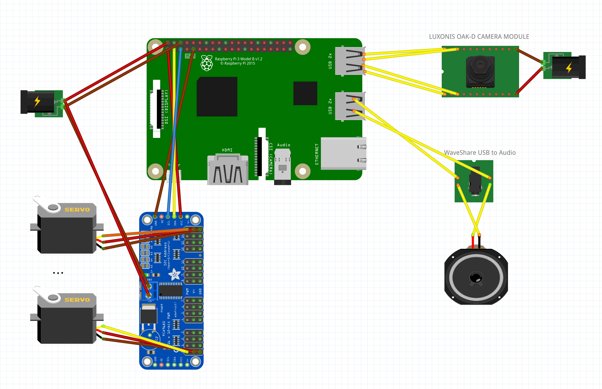
This photos showcase the "spaghetti phase"—the wiring.
The Brain: Housed in the orange enclosure is a Raspberry Pi 3 B+. To control the servos, I used a dedicated 16-channel servo controller that generates PWM signals for each motor.
Energy: The power harnesses must handle significant current spikes, especially when those powerful 40kg servos start operating under load. Both the Raspberry Pi and the servos are powered by a computer power supply (ATX), delivering 5V at a maximum of 25A.
Technical Summary:The electronic control layer was engineered for stability under high current demand.
Central Power Source: A standard ATX power supply provides stabilized 5V rails. This is essential to prevent voltage drops (brownouts) when multiple DS3240MG servos operate simultaneously under heavy load.Servo Driver: The system is driven by a PCA9685 16-channel, 12-bit PWM driver.
🏁 Final Result: The Prototype is Alive
In the final shots, we see the robot ready for mechanical testing. The dinosaur has already developed its characteristic, predatory profile. In my opinion, it looks like a prop straight from a sci-fi movie set, where authentic mechanics matter more than just computer-generated effects! :-)
Important Information:
All components can be either 3D printed (by saving the "plastic" component as an STL file) or laser-cut (by saving the "wooden" component as a DXF file) using the provided STP file. The file can be easily imported into Fusion360.
🦖 Animatronic Velociraptor - video & audio system (OAK-D + Raspberry Pi & PCA9685 & WaveShare audio card).An advanced control system for an Animatronic Velociraptor utilizing a Luxonis OAK-D camera for spatial edge-AI detection and a PCA9685 controller for servo management. The application is built on Python's `asyncio` framework, ensuring completely non-blocking, lifelike, and smooth mechanical operation seamlessly integrated with Edge AI neural networks.
🛠️ 1. Environment Preparation & InstallationFor the highest stability and native hardware support, it is highly recommended to use the Raspberry Pi OS (64-bit) or better use the dedicated depthai operating system. You can download it from (file KS_RPiOS_Full_v2.zip):
https://drive.google.com/drive/folders/1O50jPpGj_82jkAokdrsG--k9OBQfMXK5You have to extract this.zip file and use BalenaEatcher app to write image to SD card.If you insert the SD card to Raspberry Pi, you will have system ready to work - almost :-).
A. Hardware Configuration (I2C)The PCA9685 servo driver communicates with the Raspberry Pi via the I2C interface. It is disabled by default, so it must be enabled manually.Step 1: Launch the configuration tool.Open your terminal and execute the following command:
sudo raspi-configWhen the menu appears on your screen, navigate to Interface Options, select I2C, and choose Yes to enable it.
Step 2: Reboot the system.
Apply the configuration changes by restarting your device:
sudo rebootStep 3: Verify the hardware connection.
Install the I2C diagnostic tools and scan the bus to ensure the Raspberry Pi can communicate with the PCA9685 controller.
sudo apt install -y i2c-tools
sudo i2cdetect -y 1
Look at the displayed map in your terminal. The address 0x40 should be visible if the wiring is correct.
You need to install the necessary environment for OpenCV, and the servo drivers.
Step 1: Update the system.
Ensure your operating system is up to date:
sudo apt update
sudo apt upgrade -y
Step 2: Install system dependencies.
Install the required C++ libraries for OpenCV:
sudo apt install -y libopencv-dev libatlas-base-devStep 3: Install Python packages.
Download the necessary Python libraries required to run the AI and servo logic:
pip3 install opencv-python adafruit-circuitpython-servokit numpyTo allow the Raspberry Pi to communicate with the OAK-D camera via USB without needing root/administrator privileges every time, you must add a specific udev rule (use this only if you have problem with communication with OAK-D).
Remember: OAD-D must have be connected to RPi with high quality USB 3.0 cable.
Step 1: Add the Movidius rule.
Execute the following command to write the permission rule for the camera:
echo 'SUBSYSTEM=="usb", ATTRS{idVendor}=="03e7", MODE="0666"' | sudo tee /etc/udev/rules.d/80-movidius.rulesStep 2: Reload the USB subsystem.
Apply the new rules without restarting the Raspberry Pi:
sudo udevadm control --reload-rules
sudo udevadm triggerTechnology Overview
This edge-AI system uses the Luxonis OAK-D camera paired with its onboard Myriad X VPU to process a neural network model (MobileNet-SSD) without taxing the host Raspberry Pi's CPU. The calculated spatial position of the detected object is fed asynchronously into the PCA9685 controller, which generates the PWM signals to drive the animatronic's servos.
Motion Stabilization Mechanisms
To ensure fluid, lifelike movement and eliminate jitter (especially critical for animatronics), several advanced techniques are applied:
Linear Interpolation (Smoothing): The current position smoothly moves toward the target value, preventing jerky, robotic motions.
Deadzone: The system ignores micro-changes in coordinates (less than 0.5 degrees) to protect the servo gears from premature wear and eliminate continuous twitching.
🧩 3. Code Breakdown and Module AnalysisThe script is logically divided into 6 distinct functional blocks. Each block is detailed below. Full source code has line-by-line comments to explain the system's inner workings.
BLOCK 1: Imports and Global ConfigurationThis block handles the importation of the required libraries and defines the central SERVO_CONFIG dictionary. This acts as a Single Source of Truth (SSOT). The script employs a dynamic initialization sequence that pulls starting positions directly from this dictionary, protecting the hardware from uncalibrated, chaotic movements on startup.
Python
import asyncio                                     # Imports the asyncio library for asynchronous programming
import depthai as dai                              # Imports the main module for interacting with the OAK-D camera
from adafruit_servokit import ServoKit             # Imports the driver for the PCA9685 PWM servo controller
from pathlib import Path                           # Imports the Path object for handling cross-platform file paths
import cv2                                         # Imports the OpenCV library for image processing and visualization
import time                                        # Imports the time module for tracking target timeouts

# --- BLOCK 1: CONFIGURATION ---
SERVO_CONFIG = {                                   # Dictionary containing configuration for each active servo channel
    0: (60, 120, 0.04, 90),                        # Channel 0 (eyeL): (min_angle, max_angle, smoothing_factor, start_angle)
    1: (60, 120, 0.04, 90),                        # Channel 1 (eyeR): (min_angle, max_angle, smoothing_factor, start_angle)
    2: (50, 130, 0.05, 95),                        # Channel 2 (PAN): Head left/right rotation limits and speed
    11: (45, 150, 0.2, 150),                       # Channel 11 (armL): Left arm limits (150 is down, 45 is up)
    12: (45, 150, 0.2, 150),                       # Channel 12 (armR): Right arm limits (150 is down, 45 is up)
    15: (90, 200, 0.5, 90),                        # Channel 15 (TILT): Head up/down rotation limits and speed
}

TARGET_TIMEOUT = 2.0                               # Defines seconds to wait after losing target before returning to center

kit = ServoKit(channels=16)                        # Initializes the PCA9685 driver for a 16-channel servo board

# Dynamic initialization of arrays based on SERVO_CONFIG (Single Source of Truth)
target_positions = [SERVO_CONFIG.get(i, (0, 180, 0.5, 90))[3] for i in range(16)] # Creates a list of 16 target angles
current_positions = list(target_positions) # Creates a copy of the list to track current physical servo positionsThe servo_updater() function establishes a single, highly optimized asynchronous loop (~50Hz) for all active servo channels. It clamps target inputs to safe physical limits (preventing mechanical collision) and gradually moves the servos using linear interpolation.
Python
//BLOCK 2: SERVO CONTROLLER (Movement Engine)
async def servo_updater():

    while True:
        for channel, config in SERVO_CONFIG.items():
            min_a, max_a, smoothing, _ = config
            target = max(min_a, min(max_a, target_positions[channel]))
            current = current_positions[channel]
            diff = target - current

            if abs(diff) > 0.5:
                new_pos = current + (diff * smoothing)
                current_positions[channel] = new_pos
                kit.servo[channel].angle = new_pos

await asyncio.sleep(0.02)This section designs the hardware processing pipeline inside the oakd_tracker() function. It defines the Camera Node, the Detection Node (MobileNet-SSD), and the Tracker Node (Zero-Term Color Histogram). All heavy visual calculations are pushed entirely to the OAK-D's coprocessor.
Python
# --- BLOCK 3: OAK-D PROCESSOR PIPELINE ---
async def oakd_tracker():                          # Defines the asynchronous function for vision processing and decision making
    pipeline = dai.Pipeline()                      # Instantiates a new DepthAI pipeline object
    nnPath = str((Path(__file__).parent / Path('mobilenet-ssd_openvino_2021.4_6shave.blob')).resolve().absolute()) # Resolves absolute path to neural network

    camRgb = pipeline.create(dai.node.ColorCamera) # Creates a Color Camera node in the pipeline
    camRgb.setPreviewSize(300, 300)                # Sets the preview frame resolution to 300x300 (required by MobileNet)
    camRgb.setInterleaved(False)                   # Configures the image format to planar (CHW)
    camRgb.setColorOrder(dai.ColorCameraProperties.ColorOrder.BGR) # Sets color format to BGR (standard for OpenCV)

    detectionNetwork = pipeline.create(dai.node.MobileNetDetectionNetwork) # Creates a MobileNet object detection node
    detectionNetwork.setBlobPath(nnPath)           # Loads the previously resolved neural network weights
    detectionNetwork.setConfidenceThreshold(0.5)   # Sets the minimum confidence score to 50% to filter false positives

    objectTracker = pipeline.create(dai.node.ObjectTracker) # Creates an Object Tracker node to follow bounding boxes
    objectTracker.setDetectionLabelsToTrack([15])  # Tells the tracker to only follow objects with class ID 15 (Person)
    objectTracker.setTrackerType(dai.TrackerType.ZERO_TERM_COLOR_HISTOGRAM) # Sets the zero-term tracking algorithm

    xout_rgb = pipeline.create(dai.node.XLinkOut)  # Creates an XLink output node for sending the video stream to the host
    xout_rgb.setStreamName("rgb")                  # Names the video stream "rgb" for later retrieval
    xout_tracker = pipeline.create(dai.node.XLinkOut) # Creates an XLink output node for sending tracker metadata
    xout_tracker.setStreamName("tracklets")        # Names the metadata stream "tracklets"

    # Linking the Pipeline
    camRgb.preview.link(detectionNetwork.input)    # Sends camera preview frames directly to the neural network
    detectionNetwork.passthrough.link(objectTracker.inputTrackerFrame) # Sends the video frame to the tracker module
    detectionNetwork.passthrough.link(objectTracker.inputDetectionFrame) # Sends the video frame aligned with detections
    detectionNetwork.out.link(objectTracker.inputDetections) # Sends the bounding box data to the tracker
    objectTracker.out.link(xout_tracker.input)     # Sends the calculated tracking data out to the host
camRgb.preview.link(xout_rgb.input) # Sends the raw video frame out to the host for visualizationNested inside the oakd_tracker() loop is the brain of the animatronic. It uses the .tryGet() method to pull data without freezing the mechanical loops. It features two advanced core behaviors:
- Target Lock (Predator Focus): It explicitly locks onto the best_tracklet (highest confidence score), ignoring background targets.
- Auto-Centering (Idle Timeout): If the primary target vanishes for longer than
TARGET_TIMEOUT, it initiates a "standby mode".
Python
# --- BLOCK 4: DECISION ENGINE ---
    last_target_time = time.time()                 # Initializes the timer with the current system time
    is_centered = True                             # Sets the initial state flag indicating the robot is in a neutral pose

    with dai.Device(pipeline) as device:           # Boots up the OAK-D camera and uploads the defined pipeline
        q_rgb = device.getOutputQueue("rgb", 4, False) # Gets the video output queue, max size 4, non-blocking
        q_track = device.getOutputQueue("tracklets", 4, False) # Gets the tracker output queue, max size 4, non-blocking

        while True:                                # Starts the infinite host-side processing loop
            in_rgb = q_rgb.tryGet()                # Attempts to get a video frame without blocking the thread (Crucial)
            track = q_track.tryGet()               # Attempts to get tracking data without blocking the thread

            if in_rgb is not None and track is not None: # Checks if both video and tracking data successfully arrived
                frame = in_rgb.getCvFrame()        # Converts the DepthAI frame object into a standard OpenCV numpy array

                if len(track.tracklets) > 0:       # Checks if there is at least one tracked person in the frame
                    last_target_time = time.time() # Resets the idle timer since a target is actively seen
                    is_centered = False            # Marks the flag to false as the animatronic is now actively tracking

                    # Target Lock Logic: Find person with highest confidence
                    best_tracklet = max(track.tracklets, key=lambda t: t.srcImgDetection.confidence) # Selects target with highest confidence

                    for t in track.tracklets:      # Iterates through all currently tracked objects (persons)
                        roi = t.roi                # Gets the Region of Interest (bounding box) of the tracked object
                        rect = roi.denormalize(frame.shape[1], frame.shape[0]) # Converts normalized coordinates back to absolute pixels
                        p1 = (int(rect.topLeft().x), int(rect.topLeft().y))    # Extracts top-left (X, Y) pixel coordinates
                        p2 = (int(rect.bottomRight().x), int(rect.bottomRight().y)) # Extracts bottom-right (X, Y) pixel coordinates
                        confidence = t.srcImgDetection.confidence * 100        # Converts the confidence score to a percentage

                        if t.id == best_tracklet.id: # Process logic ONLY for the best target (Target Lock)
                            x = (roi.topLeft().x + roi.bottomRight().x) / 2    # Calculates normalized center X coordinate (0.0 to 1.0)
                            y = (roi.topLeft().y + roi.bottomRight().y) / 2    # Calculates normalized center Y coordinate (0.0 to 1.0)

                            target_positions[2] = 180 - (x * 180)              # Maps normalized X to PAN servo angle (0-180), inverted
                            target_positions[15] = 180 - (y * 90) + 20         # Maps normalized Y to TILT servo angle, inverted + offset

                            cv2.rectangle(frame, p1, p2, (0, 255, 0), 3)       # Draws a thick GREEN bounding box around the active target
                            cv2.putText(frame, f"TARGET ID:{t.id} ({confidence:.1f}%)", (p1[0], p1[1]-10), # Prepares the text label
                                        cv2.FONT_HERSHEY_SIMPLEX, 0.6, (0, 255, 0), 2) # Renders the text in GREEN above the box
                        else:                      # Logic for all other ignored background people
                            cv2.rectangle(frame, p1, p2, (100, 100, 100), 1)   # Draws a thin GRAY bounding box around ignored targets
                            cv2.putText(frame, f"Ignored ID:{t.id}", (p1[0], p1[1]-10), # Prepares the text label for ignored targets
                                        cv2.FONT_HERSHEY_SIMPLEX, 0.4, (100, 100, 100), 1) # Renders the text in GRAY

                else:                              # Execution path if NO people are currently detected
                    time_since_last_seen = time.time() - last_target_time      # Calculates how many seconds have passed since target loss

                    if not is_centered and time_since_last_seen > TARGET_TIMEOUT: # Checks if timeout threshold is exceeded
                        print("Target lost. Returning to neutral position...") # Prints a debug message to the console
                        for channel, config in SERVO_CONFIG.items():           # Iterates over all active servos
                            target_positions[channel] = config[3]              # Resets the target array values to the starting (neutral) angles
                        is_centered = True                                     # Sets the flag to True to prevent redundant array overwriting

                    if is_centered:                # Execution path if the robot is resting in the neutral position
                        cv2.putText(frame, "STANDBY MODE - SEARCHING FOR TARGET...", (10, 30), # Prepares the standby status text
                                    cv2.FONT_HERSHEY_SIMPLEX, 0.7, (0, 165, 255), 2) # Renders the ORANGE status text on the screen

                cv2.imshow("OAK-D View", frame)    # Renders the finalized OpenCV frame to a desktop window
                if cv2.waitKey(1) == ord('q'): break # Checks if the 'q' key was pressed for 1ms, breaking the loop to shut down

await asyncio.sleep(0.005) # Yields thread control for 5ms to let the servo_updater run smoothlyThis function sets up and launches the asynchronous event loop. It gathers the mechanical engine and the vision engine into asyncio.gather(), running them concurrently in a single thread to ensure perfect synchronization without latency.
Python
# --- BLOCK 5: MAIN SECTION---
async def main():                                  # Defines the main asyncio entry point
    tasks = [servo_updater(), oakd_tracker()]      # Creates a list containing the servo task and the vision task
await asyncio.gather(*tasks) # Runs all collected tasks concurrently in the event loopThe standard Python execution block. It safely starts the asyncio loop and catches manual user interrupts (like Ctrl+C). Crucially, it immediately releases the torque from all servos (fraction = None) upon termination to avoid continuous power draw and excessive motor heating when the script is stopped.
Python
# --- BLOCK 6: ENTRY POINT & FAIL-SAFE ---
if __name__ == "__main__":                         # Checks if the script is being run directly (not imported)
    try:
        asyncio.run(main())                        # Starts the asyncio event loop and executes the main function
    except KeyboardInterrupt:                      # Catches the manual interrupt signal (Ctrl+C) from the terminal
        for i in range(16):                        # Iterates through all 16 potential servo channels on the PCA9685
kit.servo[i].fraction = None # Cuts the PWM signal, disabling holding torque to prevent motor burnoutFor convenience, in the "code section" is the unified script ready to be executed, with full line-by-line documentation.
👀PART III. What the raptor sees?🎬PART IV. THE ENDAnd that's the end of the story of the birth of the animatronic Velociraptor. Now it's time to develop the software to increase interaction with people and produce a skeleton and skin so it's more than just a robotic skeleton. But that's a story for another competition :-)
Greetings and see you soon - MagicMarcus ;-)


Comments