

Hardware components | ||||||
_wzec989qrF.jpg?auto=compress%2Cformat&w=48&h=48&fit=fill&bg=ffffff) |
| × | 1 | |||
| × | 1 | ||||
| × | 1 | ||||
 |
| × | 1 | |||
| × | 1 | ||||
| × | 1 | ||||
| × | 1 | ||||
 |
| × | 1 | |||
| × | 2 | ||||
| × | 1 | ||||
| × | 1 | ||||
| × | 1 | ||||
| × | 1 | ||||
| × | 2 | ||||
| × | 1 | ||||
| × | 1 | ||||
Software apps and online services | ||||||
 |
| |||||
| ||||||
| ||||||
Hand tools and fabrication machines | ||||||
 |
| |||||
This is my second Arduino build. Lots of fab issues have been resolved and this is more of a bolt up than the first. Lots of functional software is being ported. Some new hardware is being added to create the ultimate alarm clock.
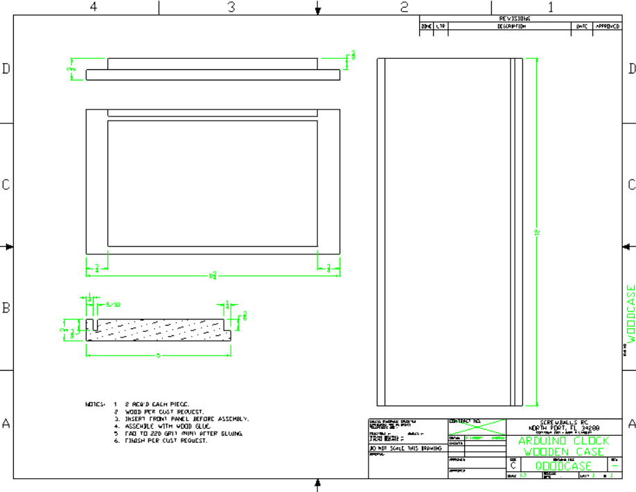
The case is made from Black Limba on the top and bottom and walnut on the sides.
The plan is to have a large, bright display that can be easily read from across the room coupled with a remote to control multiple readouts and functions. Instead of waking to just a buzzer imagine waking to any of hundreds of MP3 audio files randomly selected from existing or self recorded items.
Everything is remotely controlled but there is an alarm silence button in case you can't find the remote while waking.
The unit has a scrolling 8x8x4 dot matrix display for time display with other information available.
The MP3 player has its own speaker.
Wazzit do?A lot of things time related. First & foremost it's a battery backed up clock. Not only does the time continue running, but it retains the alarm settings as well. No more missed alarms because of a power blip.
While there is no seconds display, the clock can be precisely set. Seconds can be inferred by the blinking heartbeat LED, and the blinking colon between the hours and minutes display. The clock does something different every 15 seconds so the seconds can be anticipated.
It chimes the hour (after displaying "Cuckoo! Cuckoo!") between adjustable hours from silent to around the clock.
It always make a short "blip" sound at the top of the hour to get you to look, but the sound is mild enough not to disturb a sleeping baby.
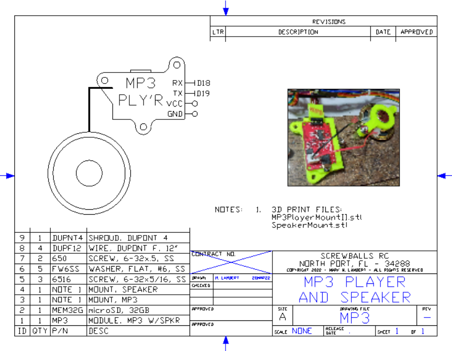
Recorded sounds can be played via an internal speaker on an internal MP3 player. These sounds are recorded on an internal microSD card permanently installed in the MP3 player module. Custom sounds available as special order.
It has special alerts at 4:20p and 8:40p.
It senses the local temperature (in °C or °F) & humidity and displays them at :15 and :45 on the minute respectively. At the bottom, :30, of the minute, the date is displayed in mm/dd/yy format.
The temp/humidity can both be displayed by pressing button 21 (2nd row, 1st col) on the IR remote. Oh yeah, the clock can be controlled from across the room with an IR remote - did I forget to mention that? (grin)
Pressing button 22 displays the date with the DoW formatted like "Saturday 3/5/2022".
The daily temp and humidity hi and lo are available under buttons 3 1 and 3 2.
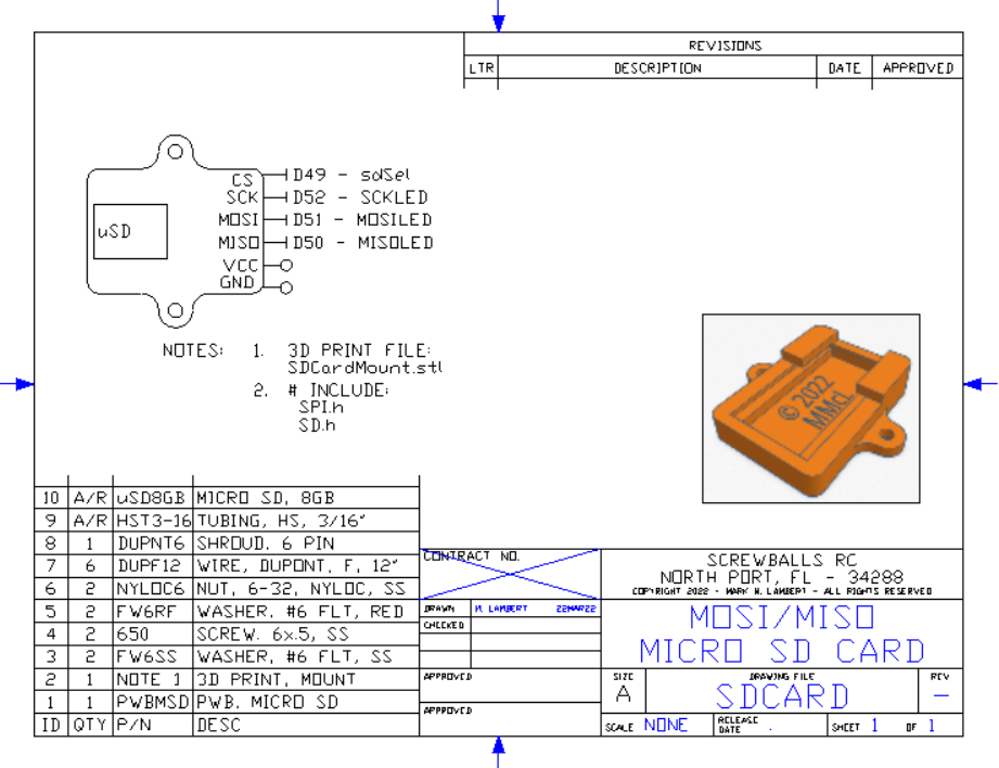
The time, temp and humidity are automatically logged to internal microSD card (accessible through the rear panel) every 15 minutes. The file is human readable ASCII and named "logmm-yy.txt" where mm-yy is the current month/year. The 32gb microSD card should be able to hold a CENTURY of data.
Anyway the time can be displayed in standard AM/PM or 24 hour format. Toggle between them with remote button 1 3.
Likewise the temperature can be shown in °C or °F by pressing button 2 3.
The unit has a switched AC outlet that comes on with the alarm (coffee pot) and turns off an hour later automatically. If the power blips, the coffee pot outlet automatically disables. The outlet can be manually controlled by pressing button twelve on the IR remote.
The brightness of the display is controlled by the knob. There are a total of 16 brightness levels. The display can be instantly dimmed with a single press of button 7 2 (bottom center). Likewise, the sound is muted with button 7 3 (bottom right).
Row 4 controls the alarm functions:
- 4 1 - Display alarm state & time
- 4 2 - Toggle alarm state on/off
- 4 3 - Set Alarm time
The alarm on/off status is shown by the red indicator on the "traffic light" display. Pressing button 4 2 will toggle both the alarm state and the red traffic light indicator. If the alarm is disarmed (off) the unit will beep twice as an audible confirmation.
The traffic light's green LED is the "heartbeat" that ticks on or off once a second any time that the time is being shown.
The yellow LED shows the state of the coffee pot (aux) outlet. The indicator will be on whenever the outlet is energized. As previously mentioned, the outlet can be manually controlled with button 1 2.
IMPORTANT NOTE:
The auto-off feature does NOT occur if the power was manually commanded "On". Once manually commanded on, the outlet will remain energized indefinitely until manually commanded "Off" or the unit is reset by button or power cycle.Setting the Alarm:
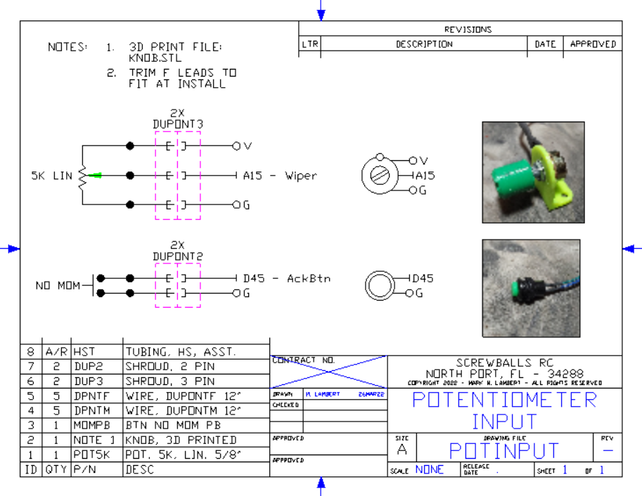
Entering information is done with a potentiometer and a button. This same button is used to silence the alarm. The potentiometer (pot) is ranged with lower values when rotated left and larger values right. The pot only rotates about 270° degrees, so don't force it past its stops.
The input is prompted and the pot is used to "Dial" in the response value. The display is continually updated as the pot is rotated. Once the desired value is shown, pressing the metal Acknowledge (Ack) button next to the pot will select the value. The unit will beep as each entry is accepted.
After pressing the Set Alarm button, button 4 3, you will be prompted to select the alarm hour. The hour is shown on the display as HH:xx in modified 24 hour format (no leading zero). The hour values range from '0' to '23'. Pressing the Ack button advances to the minute entry.
The minute for the alarm time is entered similarly with the range of '0' to '59'. The entry display shows the selected hour in the format "23:mm". Selecting the minute with the Ack button completes the alarm setting and automatically arms the alarm (as shown by the red traffic LED).
Using the Alarm:The alarm is automatically enabled after setting. At the specified time the unit will display "Wakey! Wakey!" and chime 10 times. Pressing the Ack button on the top will silence the alarm. Failing to Ack the alarm will cause it to repeat a total of three times before giving up.
Setting the Time/Date:Setting the time should only be needed on time changes or after battery (CR2032 coin cell) replacement.
Setting the time and date is similar to setting the alarm time but with additional data entries for month, date, year and day of the week (DoW). Additionally it is possible to just set time portion and leave the date and DoW alone.
Since Setting the time is a rarity an "Are you sure?" confirmation is needed to start the process to allow the user to bail out after an accidental press of button 33.
Dial the pot to '00' for 'No' and '01' for 'Yes'
Having selected to continue you will be prompted to enter the time hour and minutes in the same manner as the alarm.
At this point you will be asked if you wish to enter the date and DoW. Again use '00' for no and '01' for yes.
The date is entered with the month displayed as '1' to '12' as in "mm/xx". Having selected the month the date can be entered as '1' to '31'. Don't try to enter February 30th please.
The year is prefixed with 20 and can be varied from '2000' to '2099'. Attempting to enter a year below '2022' will cause the system to beep and retry until a valid year is selected.
Entering the DoW allows you select from the following days:
- 01 - Sunday
- 02 - Monday
- 03 - Tuesday
- 04 - Wednesday
- 05 - Thursday
- 06 - Friday
- 07 - Saturday
After selecting the DoW or having just entered the time the user will be prompted to sync with the command "NOW!" and the system will hold on a press of the Ack button. The time, date, and DoW will be entered and the seconds reset to '00' at the moment the Ack button is pressed. This allows exact to-the-second setting of the clock.
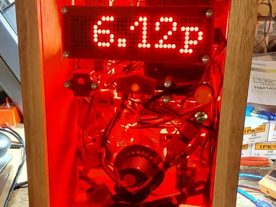
Cabinet and Hardware:The entire clock is housed in a shoebox shaped wooden and Lexan box. The front houses the scrolling LED matrix kthe 'ticker'), the IR remote receiver module, and the Traffic Light indicator. All three components are mounted behind a transparent smoke grey Lexan plate. The IR remote receiver is mounted at the top left and this is the point at which the user should aim the remote.
The Lexan is framed in wood. The sides, top and bottom are wood. The back is clear Lexan to show the blinking internal LEDs as the unit operates.
The clock power is via a 5V "wall wart" power supply with a 5.5x2.1mm jack. The coffee pot power system is not required for normal operation and is electrically independent of the clock circuitry. Other than two K2 relay terminals, the highest voltage inside the box is 5VDC.
Modules:Internally the unit consists of a handful of assorted Arduino modules attached to 3D printed mounts screwed to a Lexan baseplate with stainless allen head cap machine screws with nyloc tamper-proof nuts. All power & ground leads are soldered to buss bars while the signal lines connect to the screw terminals.
The normally separate DuPont connections are ganged and glued into 3D printed shrouds and labelled. This reduces wiring errors and increases reliability. It also simplifies & speeds servicing.
It uses the following standard Arduino components:
- CPU - Mega 2560 clone w/screw terminal shield & EEPROM (non-volatile) parameter storage
- 8x8x4 red LED scrolling matrix display
- RTC with CR2032 coin cell battery backup
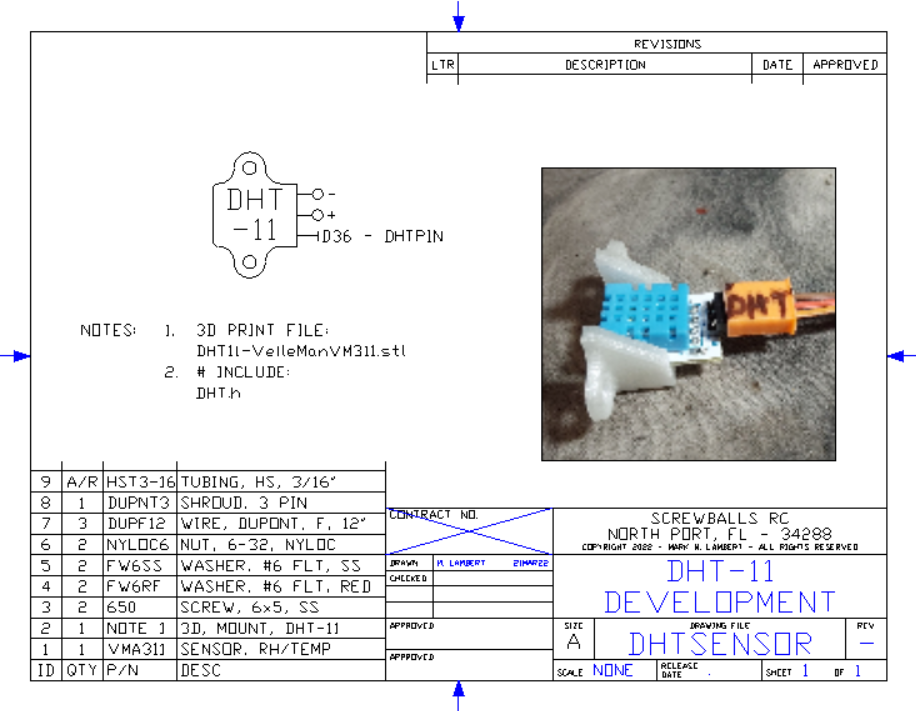
- DHT-2 2 digital humidity/temperature sensor
- microSD card reader/writer for temp/humidity logging
- R/Y/G traffic light display
- Serial control MP3 player w/amp & speaker
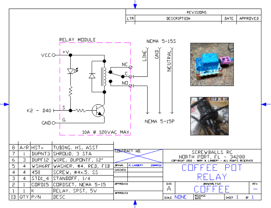
- SPDT 5v relay
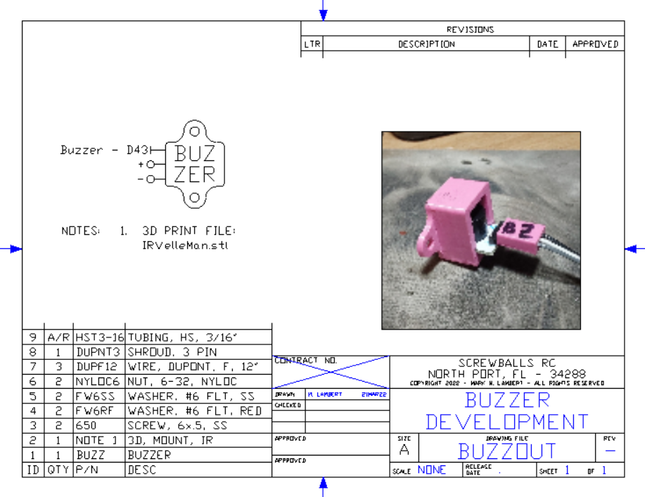
- Active buzzer
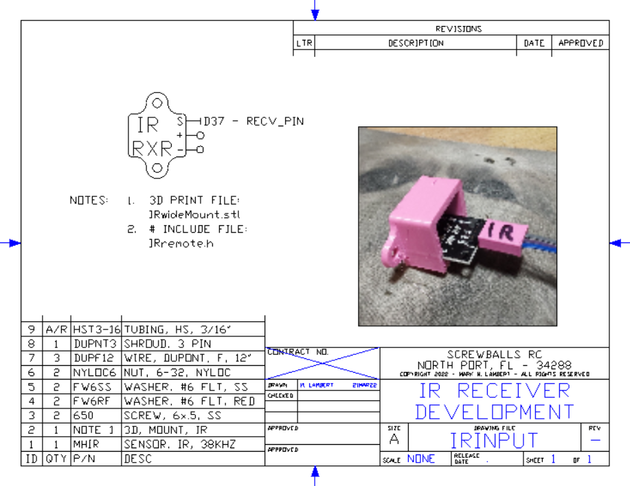
- IR remote receiver and handheld remote
- Assorted DuPont connections with shrouds and HS tubing banding
Additional electrical components include:
- 5k analog data entry potentiometer & 3D printed knob
- Acknowledge (Ack) and reset push buttons
- 5v power supply
- UL approved AC inlet & cordset for aux relay
- UL approved switched AC outlet (NEMA 5)
- 3D printed Vcc & Gnd buss bars
The DuPont connectors are easy to use and reconfigure, but tend to be fragile. Trying to make a product designed to last for YEARS requires a more reliable connection.
Each sensor usually requires both Vcc and Gnd. The screw shields bring out all of the Mega's pins, but the Mega only has a few ground and Vcc pins. Traditionally power bussing requires a stack of DIN rail terminals that are neither small nor cheap.
I 3D printed a couple of buss bar holders that give a three inch piece of 12 ga wire support. You then wrap the Vcc and Gnd leads around the buss wire and solder. This looks messy by really isn't.
The basic DuPont cable is a series of ribbon cable wires with individual loose ends. The first step is to thread a shroud over the wires and super glue it in place.
Once the shroud has set, heat shrink tubing is added to the cable near the shroud and again near the middle. This keeps the cable wire from splitting.
The near end of the cables have the two power leads separated out and banded with heat shrink.
The power leads are stripped about an inch, while the signal leads are stripped shorter. All leads are tinned and then trimmed to final length.
Each devices cables were pre-made and labeled. This greatly simplified wiring. cable length isn't an issue as M-F cables can be used as extensions where ever needed.
Clockwise from top left: RTC module with battery. Traffic light with 3D printed Greek Revival cover. Red is Alarm On, yellow is aux relay (coffee pot) state. Green is the heartbeat indicator.
K2 is the coffee pot relay. K1 is not installed.
Finally we have the IR sensor. These devices are very sensitive to power levels and if your nearing the 200mA limit of the card, the IR remote will only work erratically or not at all. The shroud also keeps extra light off the sensor.
Clockwise from top left. Relay K2 again. The buzzer fits in the same holder as the IR receiver. The boost converter. A DHT temp and humidity sensor.
Fab:At this point the hardware is solid, the software is clean, the wiring has been trimmed and it's time for some fab.
I love using Lexan as a material. You can get it clear, tinted, transparent color, opaque color, and its easy to machine at my desk. Great stuff. In this case I have a piece of mirror Lexan 8x12. The plan only calls for 8x8, but why not? A couple of the items hadn't had their mounting locations settled and having some reserve space is always good at this stage of development.
Everything is mounted with #6 or #4 SS allen head cap machine screws with red fiber washers, ss washers, and nyloc nuts.
All the 3D printed mounts had been reprinted in copper silk. Some of the wiring shrouds were done early on and I'm not going to replace perfectly good, functional, wiring for a purely aesthetic issue.
The Mega is hiding under the screw terminal shield, everything not front or rear panel mounting is attached here.
The little device PC cards have been secured in their mounts with a couple of small dabs of gel superglue, The shrouds hold the pins in place and increase connection retention force. They also give a place to label the connectors.
CW from top left:
- The IR sensor, traffic light, Ack button and selector pot will all mount on the front panel.
- MP3 player and 2" speaker with micro SD memory (hidden) for wake up messages.
- micro SD weather logger and coffee pot power relay
- Buzzer, DHT-11 (foreground) glued into mounts, Vcc/Gnd buss bars (pink)
CW from top left:
- Micro SD data logger and coffee pot power relay showing wiring
- 5VDC power feed from 20W (5V @ 4A) wall wart switching power block.
- Coffee pot outlet mounts in 2" dia hole and is prewired.
- Complete electronics package waiting on rest of case.
I'm building a 2nd copy that will have much neater wiring. In the prototype here, the leads were left long as the mech layout wasn't settled. Now that I have a reference layout, the cables can be cut to fit prior to connection.
I printed the layout 1:1 on the laser. I'd planned for 8" wide material with 1/2" for margin. The 8-1/2x11 paper printable area was just enough to print it perfectly to scale. I simply taped the pattern down on the material and drilled ONE 1/16" pilot hole for each of the mounts. Following with a 5/32" bit (#6 thru) allowed me to mount the actual piece in place. I then used the same 5/32" bit to drill the remaining mounting holes. The outlines weren't perfect and didn't have to be since the pattern was only used for the first hole. All the rest were taken using the final 3D printed parts as a drill guide.
Using the preset layout really sped the fab process. Some items, like the speaker, didn't have a mount designed until last thing so I couldn't predict exactly where/how it would mount.
Initially the design called for parts to mount top, bottom, front & back. This presented some assembly problems that were eliminated by not using the top as a mount. The dimensions have been morphing as I find different materials. SWMBO, who is getting unit #2 has requested a completely transparent case in a variety of Day-Glo colors.
For the base of the 2nd unit I'll use 1/4" instead of 1/8" Lexan. This so the Lexan itself can be drilled & tapped, eliminating the need for longer screws and nuts. Even tho' the Lexan has doubled in thickness from 1/8" to 1/4", using the thicker Lexan will save having projections below the plastic, saving 3/8", for a net 1/4" space savings and a smooth baseplate.
Front Panel Fab:As with the base, the front is made from Lexan, red in this case. The parts to be mounted were sketched, the sketch taped to the panel and one pilot hole drilled for each device with a 1/16" bit.
Nothing in the layout was critical, but I tried to be neat. The holes are easily drilled with small hand tools. Once each part had one hole drilled, the actual bracket was mounted and the addition mounting holes drilled using the actual bracket as a guide. This allowed rapid and precise drilling of 11 different holes. Step or cone bits were used to enlarge the 5/16" and 7/32" holes for the pot and Ack button.
Everything was mounted with with the supplied hardware for the pot and button, or with 6-32 SS Allen cap head machine screws and hardware. Each screw has a red fiber washer under the head and a #6 SS flat washer on the back side under the nyloc nuts.
The two pieces were then reconnected and tested and everything still worked. First, do no harm! LOL
The panel spacers are 3D printing now. I figure I need at least four if not six. They're printing in a grape purple PLA filament that we accidentally bought extra of and I can burn all of it I need.
I'd been stuck on the physical mounting of the front and had been working with the concept of a sorta-shoebox thing with the red up front and the top clear and the bottom mirror. But mechanically and cosmetically it just wasn't jelling.
Flash! Instead of table top, make it a wall hanger! The top is now the front and the front is now the top! So the top can be wood as will be the sides and bottom while the back is mirror and the front is RED! Like, way cool, dude.
Once that decision was made, the rest just flowed out and in just an hour or so working quietly at my desk, the panel was working out.
Clockwise from top Left:
- Layout taped to red Lexan and hand driver with 1/16" pilot
- First hole approved by my supervisor
- Front of panel - SS screw caps, pot knob and Ack button
- Rear of panel - Everything mounted with SS #6 hardware
Once the hardware was installed, hooking it up was easy enough.
Clockwise from top Left:
- Neatly mounted
- Side view after first two supports loosely in place
- Display looks good with red
- 3/4 view showing innards
<blockquote>
Ammeter:One accessory that every Arduino maker should have on their bench is a simple ammeter. Working with Arduino I've found the power distro native to the mega 2650 and UNO to be lacking. When the spec says 200mA total, it MEANS it. Powering the cards via USB causes the on board voltage to drop to 4.3V as the anti-backflow diode loses ~.7v. It doesn't take much to sop up 200 mA. In this project the scrolling LED's can draw up to 1A if all pixels are maximum brightness.
With this $15 analog 0-3A DC ammeter, you can see the current wax & wane as the display changes and the relay is energized. The peak current is around .6A, well beyond the .2A max for the Mega.
</blockquote>
The IR receivers have given me fits with them failing to trigger no matter what. FINALLY it was traced to a soft Vcc line. At 5.0V with 4A behind it the IR response is solid as a rock, as is all of the other functions.
S/N: 000000002 (Optimistic, ain't I?)Knowing the circuitry was right allowed me to go ahead on unit #. Same parts & program, better build.
On the first unit everything had to be wired BEFORE the mechanical issues were addressed. Thus there was a lot of spaghetti and generally messy wiring.
I'm also incorporating several "Lessons Learned" from the first build. The biggest of which was the upgrade from 1/8" to 1/4" material for the base. The 1/4" thickness is thick enough to thread for mounting. this eliminates nuts and washers projecting out the back/bottom. The outer frame of unit #1 will cover the exposed hardware, but #2 will have a smooth back.
Again, I printed the CAD layout 1:1 and piloted just one hole on each device. Then those holes were drilled and tapped 6-32 and the actual devices mounted. With the devices, but no wiring, in place, it was a simple matter to precisely locate and drill the remaining mounting holes.
All the remaining holes were tapped 6-32 and the mounts installed. Care is used not to drill or tap too quickly as the plastic tends to melt. SS Allen head cap screws and SS washers are used throughout,
The pink mount for the Mega was just used for piloting and was replaced with the final mount.
Tip: Tin the buss bars! This GREATLY aids in soldering.
The screw terminal shield was marked with color Sharpie, red on the +5VDC terminals and black on the Gnd terminals. All of the terminals were unscrewed to make it easier to wire and also see what terminals have and have not been used.
The AckBtn and Reset buttons are direct wired to the to Mega, consuming two of the "spare" ground leads. The have connectors so the unit is separable.
<blockquote>Part of the design rules are that all units are separable for servicing. No soldering is needed to R&R any element. except the main buss bars themselves (something that should NEVER fail).
Another design rule is that no power pins are exposed. Servo motors have female connectors requiring male power pins to be exposed when unplugged. This is strictly Verboten! in my designs (even though there are no servos in THIS project, it serves to illustrate my point -- hot pins BAD!)</blockquote>Once everything was secured, the actual wiring could begin. This time, the cable are fitted and cut to length instead of being left long. As you can see, the wiring is MUCH tighter and neater. Wiring isn't complete, but you can see how much cleaner the layout is.
The build is coming along nicely:
Left to right, top to bottom:
- Mega mounted on base
- Mounted on panel with screw terminal shield, power buss, buzzer and DHT-11
- Wiring in process. Note the dressing
- Closer look, much neater, eh?
The schematics and 3D .STL files have been alphabetized for easier reference. I'm still polishing the docs, but it's coming along.
Success!:Well, THAT didn't take long! Up and running just a few hours after starting! Clock runs, keeps time, all functions operating. Retains time & settings over power loss, in other words, its good to go!
The ammeter shows the draw at ~1/2A with time displayed at full brightness. During initialization two full squares lit up drawing almost 2A! you'll not run THAT off USB power!
<blockquote>One of the little things I do during the prep is to mark the power and ground terminals with red and black Sharpie. This helps keep track of where you are in the nest of terminals and makes a good visual reference. I also unscrew all of the terminals so the wiring goes faster and you can easily tell used from open pins.
Marking and unscrewing the terminals only takes a few minutes, but it really helps in assembly and troubleshooting.</blockquote>The completed wiring is much nicer looking and only took a fraction of the time to wire.
The pieces hanging off the table are attached to the as-yet-unbuilt front panel.
Not bad if I do say so myself.
Fab Nears Completion on Unit #2:Having the locations finalized allows the wiring to be fitted. The front from Unit #1 was married to the back from Unit #2 to form a new, neat unit.
Unit #2 is built on 1/4" Lexan, this is necessary as I found that the 2" diameter outlet is too big to be drilled into 1/8" plastic without shattering.
SWMBO doesn't want the outlet so that one can be smaller. I'm going to build a new front panel for hers. She wants hers out of UV glow green transparent Lexan with a smoke grey front. It's all going to be held together with 3D printed struts.
Anyway, it's amazing what some cable dress does for the overall appearance.
The left is the front panel and the right is the 1/4" thick rear panel. The devices are screwed into threaded holes on the 1/4" thick panel. This simplifies assembly as only one side needs to be accessed to mount. The ammeter is clipped onto the buss bars for test.
The software reads the pot position in real time and updates the display brightness smoothly (as smoothly as possible as there are only 16 brightness levels) as the knob is rotated. The current reading on the ammeter tracks the knob as the brightness changes. During the time the display is blanked, the current falls to ~200mA. When the display is showing the time at maximum brightness the current demand rises to 500-600mA. If all LED's are on, the current heads to 2A!
The leads have been bundled and tied, excess lengths folded and tied, neat and reliable wiring for long project life.
The right side is the base with the Mega 2560 and all the other related support electronics.
The microSD card at the top left was wired in after these pics were taken. Below it is the RTC with the CR2032 coin cell. The red card below that is the MP3 player. The speaker is free hanging for now.
Below the Mega is the Vcc and Gnd buss bars, below that is the buzzer and DHT-11. The DHT-22 upgrade (better precision) is on order.
The green and black reset button is visible thru the LRHC of the rear panel. Everything was tied together after being trimmed to length. The over all appearance is much more professional than the original wiring.
The second unit came right up without problems. Careful work helps.
Waiting on the 2" hole saw to mount the coffee pot outlet. The relay needs to pass thru the hole as it's prewired so THAT has to wait to mount as well.
Everything else seems to be working solidly. The red front and solid power supply voltage has greatly improved the reliability of the IR remote. The mount narrows the FOV somewhat, but on target commands work almost 100% of the time. The software indicates significant noise on the IR input. Random numbers keep getting received. This is more pronounced when there are LED lights nearby (my bench magnifying 100W LED lamp). Moving the light so it doesn't shine directly on the sensor mostly eliminates the issue.
The 2" drill came and the coffee pot outlet is mounted.
I'm at the point where It needed a case. I had a stick of walnut that was long enough for the sides but not for the top and bottom. I had a slab of black limba kicking around and it was perfect for both the top and the bottom, After about an hour in the wood shop, the case was ready.
The front panel is captive in the case. but the rear panel can be removed for access to the change the coin cell or extract the logged data on the microSD card.
The only part missing is the power inlet. You can see the stub clipped to the ammeter.
Both the front and back are transparent and when back lit the entire unit glows red.
Anyway, you can see how cool this looks.
Final project (more or less).
Hope that this has been instructive. Please comment. I did my best at-home engineering with this, It took a reel of 3D filament and a couple of hundred $ worth of electronics and Lexan, but I think the effort was worth it, don't you?
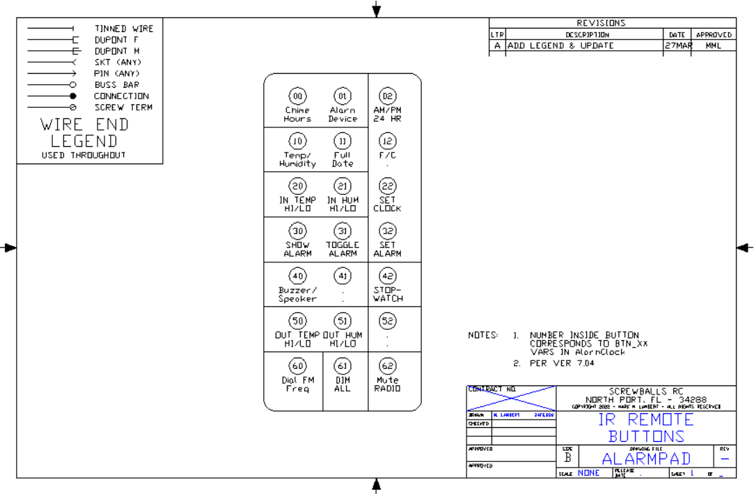
Legend and Remote Control Functions
All other pages are in alphabetical order. See block diagram in STORY for devices.
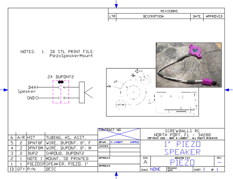
1" Piezo Speaker Assembly Drawing
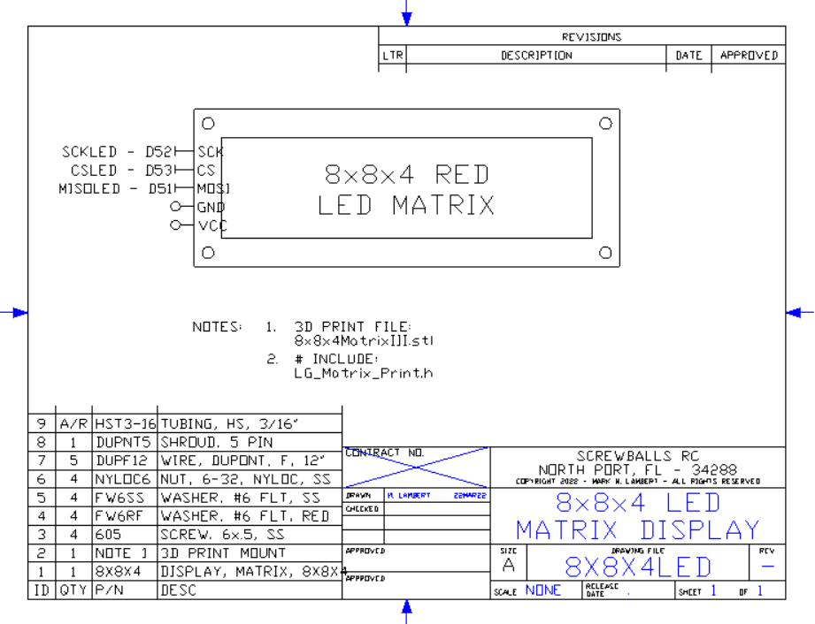
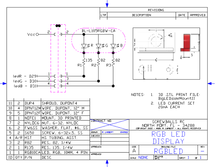
8x8x4 LED Matrix
Scrolling LED display is large and easily readable from across the room. Scrolling function allows long messages to be displayed while short static messages can also be shown. Intensity adjustable to 16 levels.
Coffee Pot Relay Circuit
The relay is peak rated at 10A @ 125VAC, however for safety, its de-rated to an 800W limit.
DHT-11 Sensor Development
Used to capture temperature and humidity data. Plan is to upgrade to the higher precision DHT-22 in the future.
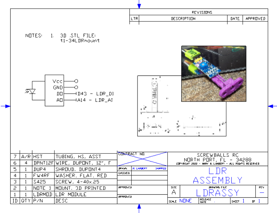
Micro SD card
MP3 Player
Two 3D mounts are needed, one for the player and a second for the 2" speaker.
Potentiometer and Button Input
This is a fast and intuitive entry method and can be scaled from just two choices to 100 with smooth response.
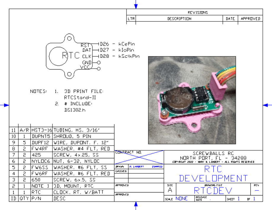
RTC Development Drawing
Clock uses common CR2032 coin cell for time keeping over power down. Clock is sensitive to PS glitches. Turn off power before connecting.
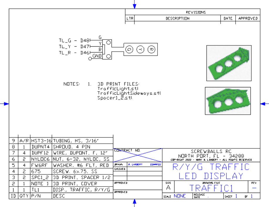
Traffic Light Display
Three color LED's are used as follows:
RED - Accessory Power ON
YEL - Alarm Set
GRN - Heartbeat (hard to see thru red lexan)
Mounting includes two optional decorative covers. One vertical, one horizontal, both in classic "Federalist" style.


_t9PF3orMPd.png?auto=compress%2Cformat&w=40&h=40&fit=fillmax&bg=fff&dpr=2)


Comments