
Hardware components | ||||||
 |
| × | 1 | |||
 |
| × | 1 | |||
 |
| × | 1 | |||
 |
| × | 1 | |||
Software apps and online services | ||||||
 |
| |||||
Whole tutorial in video:
In this simple example, Google Assistant will control:
- LED diode – switching on / off, that is, sending boolean values by Google Assistant
- servo mechanism – after the voice command the servo mechanism moves to the position – by Google Assistant
We will use IFTTT and RemoteMe. In IFTTT, we can easily add voice commands to your Google Assistant, which will call a “trigger” in IFTTT and this will call the http query to change the variable in RemoteMe. The RemoteMe will forward command to the ESP. And the ESP will change diode or servo mechanism state.
The Google Assistant will control two variables:
- boolean type – LED diode
- integer type – servo mechanism
After adding the variables, ESP will be “observing” it, then after variable value is changed by the google Assistant our ESP will be notified.
Adding Variables
Name of Boolean variable is RELAY_01 – with this name it will be easier to add later android application to control it. more about variables here.
The same we are creating integer type variable with the name “servo.”
Now we have to send variable change into ESP.
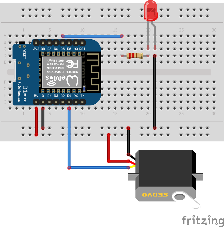
ESPConnectionsServo mechanism
- Vcc to ESP 5V
- GND the the GND of the ESP
- Contorl wire to D1 ( check before if your servo mechanism can be connected to 3.3V pin, otherwise use logic level converter)
- Diode to D5 through resistor to ground
After we change variable the ESP will set diode or servo mecahnism to given state.
We will start by generating the code with the functions needed to collaborate with variables.
To add a device to RemoteMe, go to the “Devices” tab, then “New Device” and “New Network Device” in the window enter:
Then click “Submit” more here.
To generate the code, click on the Burger Menu and the “Code Generator Wizard:"
In the first step, we select all variables, this will generate the appropriate code where the function will be created for the variable manipulation and called when variable is changed more about the wizard here.
In the second step, enter the name of our wifi network and the password to it (we can not enter anything and complete it later in the code).
In the last step, we display the generated code and paste it into the Arduino IDE. Below the code completed with the implementation of the servo control mechanism and the led diode.
#define WIFI_NAME "nameofwidi"
#define WIFI_PASSWORD "wifi password"
#define DEVICE_ID 1
#define DEVICE_NAME "ESP"
#define TOKEN "token"

#include <RemoteMe.h>
#include <RemoteMeSocketConnector.h>
#include <ESP8266WiFi.h>
#include <Servo.h>//ADDED

uint8_t LEDpin = D5;//ADDED
Servo myservo; //ADDED
RemoteMe& remoteMe = RemoteMe::getInstance(TOKEN, DEVICE_ID);

//*************** CODE FOR CONFORTABLE VARIABLE SET *********************

inline void setRELAY_01(boolean b) {remoteMe.getVariables()->setBoolean("RELAY_01", b); }
inline void setServo(int32_t i) {remoteMe.getVariables()->setInteger("servo", i); }

//*************** IMPLEMENT FUNCTIONS BELOW *********************

void onRELAY_01Change(boolean b) {
    digitalWrite(LEDpin,b?HIGH:LOW);//ADDED
}

void onServoChange(int32_t i) {
     myservo.write(i);//ADDED
}

void setup() {

    WiFi.begin(WIFI_NAME, WIFI_PASSWORD);

    while (WiFi.status() != WL_CONNECTED) {
        delay(100);
    }

    remoteMe.getVariables()->observeBoolean("RELAY_01" ,onRELAY_01Change);
    remoteMe.getVariables()->observeInteger("servo" ,onServoChange);
    remoteMe.setConnector(new RemoteMeSocketConnector());
    remoteMe.sendRegisterDeviceMessage(DEVICE_NAME);

    myservo.attach(D1);//ADDED
    pinMode(LEDpin, OUTPUT);//ADDED
    digitalWrite(LEDpin, LOW);//ADDED
}

void loop() {
    remoteMe.loop();
}
New lines are mark by //ADDED
#include <Servo.h>
A library for servo control mechanism – it must be added before, as well as the RemoteMe library more here.
void onRELAY_01Change(boolean b) {
    digitalWrite(LEDpin,b?HIGH:LOW);
}
void onServoChange(int32_t i) {
     myservo.write(i);
}
Function called when the Googel Assistant changes our variables.
    myservo.attach(D1);
    pinMode(LEDpin, OUTPUT);
    digitalWrite(LEDpin, LOW);
Setting the servo mechanism and pins for controlling the LED.
After these modificationswe upload our sketch.
TestingOur ESP after upload sketch and power on will connect to RemoteMe:
And after going to the variables tab and expanding them:
ESP – in variables means that our device listens for variable changes.
let’s change the variables and see if the diode and servo mechanism reacts accordingly. From the burger menu select the “Set …” option
And in the window that appears we change the value of the variable and click Submit. Our diode and servo mechanism will react.
Generating links to change variablesIFTTT will be like the “Set …” function, change the value of a variable, but IFTTT will do it by calling the http query appropriately. Let’s generate a simple link to the GET method:
From the variable menu burger, click on “Generate Set Variable Link:"
Generated link:
https://app.remoteme.org/api/~155_D49LDj@aBFhK./rest/v1/variable/set/variableValue/RELAY_01/BOOLEAN/false/
After copying the link and opening it in the browser (even in incognito mode – where we are not logged in ), our LED will turn off, the URL is using one of our tokens, that’s why it works even if you are not logged in.
To generate a link to light up with a diode – change “boolean” to on and click “Generate” we will get a link after calling which our diode will light up.
IFTTTLet’s create an Applet for voice control:
- adding a Google Assistant with the “turn light on” command.
- adding a connected “Webhook”, which will call the appropriate query on the RemoteMe, just like the links from the example above will turn on the diode.
In IFTTT, we go to My Applets, then New Applet, after clicking on “+ this”
We choose Google Assistant:
And then “Say a simple phrase," we complete:
(Note: phrases such as “turn light on” can already be assigned to the default command in the Google Assistant – so when we get a different response after calling a voice command than “OK preforming action” we have to choose another voice command).
And click create trigger, then click “+ that” and choose webhooks:
And “Make a web Request” and fill with data generated by RemoteMe.
Let’s generate:
In this case we chose the “use Post Method” option (the POST method is more elegant to change the variables state than the GET method) and generated a link and POST query content that will enable the LED.
After pasting into our webhook it should look like this:
(Don’t forget to change Method to POST and Content Type to application/json.)
We click “create action” and “finish”. After a while, when our account on Voogle Assistant is updated, we can say “ok google, turn on ligh” and our diode will be turned on.
Similarly, we create actions for the phrase “turn off light”, remembering to generate a link in remoteMe with the “boolean” option set to false. Now we can turn the diode on and off with the help of the Google Assistant.
IFTTT – servoLike a diode, we can generate a command to control the servo mechanism, but in this case we will say in the command a number that will be properly recognized.
We create a new applet similarly to the previous one, but now in the Google assistant we choose “Say Phrase with a number” and we complete:
In the “Set servo to #” command instead of # we will tell the number that will be recognized. Let’s insert the URL, modifying the “body” generated by RemoteMe with the appropriate “tag” after pasting the webhook should look like this:
IFTTT will replace in the called {{NumberField}} json by the number we say to the Google Assistant.
Our Applets look like this:
Then from the Google Assistant, we can change our diode and the position of the servo mechanism. The movie from 10:40 shows the action:
Bonus – control via a websiteWe can also easily create a website – hosted in the RemoteMe cloud to control our ESP.
We choose “new Device," “New WebPage” then fill:
After adding, extend the belt website, click on index.html and choose “Edit With wizard."
Then click on the Insert Component and complete:
The name property insert by clicking the “magnifying glass” we will minimize the mistake when entering the names of the variables. After clicking “Insert” add the component to control the servo mechanism:
After adding, close the wizard, click on index.html and choose “Open in new Tab.”
By clicking the switch we turn off our led, and by moving the slider we change the positions of servo mechanism.
We can open the website on a mobile phone, the easiest way to scan the QR code generated by clicking on index.html -> “Get anymous link” and clicking the QR code icon, after display the QR code we scan it with a smartphone and we have access to website control.
Bonus – controlled by mobile applicationsThere is an application – provided by Nguyễn Duy Hiếu available here.
Which, when connected to our account, allows us to control our diode – from the Relays tab (of course, because we called our variable RELAY_01 diode at the beginning).
This simple tutorial shows the basics how by invoking http queries change variable states, i.e. by IFTTT.
I encourage you to create your own examples.
Comments