


Hardware components | ||||||
| × | 4 | ||||
| × | 4 | ||||
 |
| × | 4 | |||
 |
| × | 1 | |||
| × | 4 | ||||
Software apps and online services | ||||||
| ||||||
 |
| |||||
| ||||||
Hand tools and fabrication machines | ||||||
| ||||||
 |
| |||||
 |
| |||||
| ||||||
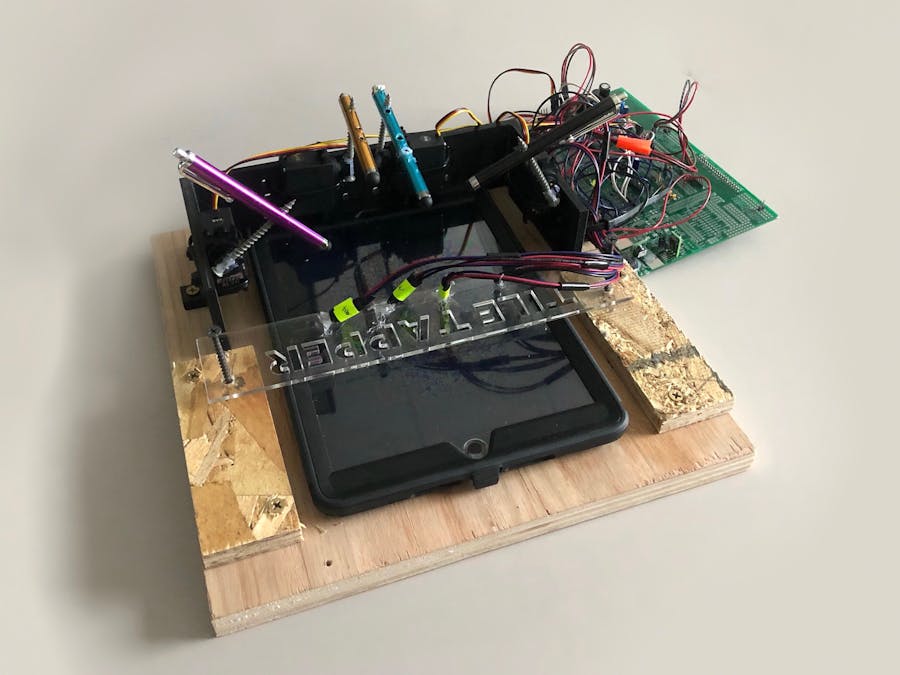
The Tile Tapper is an entirely TI MSP430-controlled robot designed to play the iPad application "Piano Tiles". To do this, photoresistors are used to determine whether a given tile passing across the screen is black or white. This information is then used by the four corresponding motors to tap the styluses and hit the tiles at the correct time.
TheCode
Timer A: Happening in the MSP430 Timer A, the ADC10 DTC (Analog-to-Digital Converter, Data Transfer Control) is used to read the four photoresistors and send their values to a global four element integer array once every 0.5 ms. In the ADC10 ISR (Interrupt Service Routine), these four photoresistors are correlated with specific motors and given thresholds for their readings. These thresholds determine whether the motor is seeing white or black, and thus whether the stylus should be tapped on the screen or not.
Timer B: Happening simultaneously in Timer B, the "up" or "down" commands are used to set the duty cycle for manual PWM signals using digital I/O pins for each motor. The clock is looping a counter every 20 ms in order to create a PWM frequency of 50 Hz, as is required by the servo motors.
MechanicalDesign
The initial prototype was made using card board, zip ties, and glue for rapid assembly. This allowed for effective proof of concept and ultimately determined the placements for the motors, photoresistors, and wire lengths for the final design. In Figures 2 and 3, the cardboard prototypes for both the photoresistor holder and the motor casing are shown. For the final design, 3D printing was used to fabricate the casing that holds the motors in place. Acrylic was cut and used to hold the photoresistors above the tile columns to read the tiles in each of the four rows. The final prototype is shown in Figure 4.
PainPoints
Software:
The most prominent issue to be tackled during this project was the limited number of timers available on the MSP430. Knowing that Timer A would ultimately be used solely for reading photoresistors and storing them globally using the ADC10 DTC, determining how all four servo motors would be controlled using PWM signals within one timer became a challenge. This challenge was ultimately tackled by manually setting digital I/O pins high and low with the right timing to create the necessary PWM signals for the motors.
The next challenge was determining a proper speed for the timer. Initially a clock period of 0.1 ms was used for both timers so the photoresistors would update quickly and the servo motors would respond nearly immediately. Servo motors expect an input signal with frequency 50 Hz, or a period of 20 ms. Using a clock period of 0.1 ms allowed us to use 200 clock cycles to produce our PWM period. The full range of the servo motors can be controlled using PWM duty cycles from 3% - 13%, or 6 - 26 clock cycles high while the rest are low.
A clock period of 0.1 ms ended up becoming problematic, as the microprocessor was unable to sample and convert in the DTC as well as switch the I/O pins fast enough to produce a frequency of 50 Hz, rendering the motors unusable.
The final clock period is 0.5 ms, a balance between sampling speed and the ability of the MSP430 to produce a PWM of 50 Hz. This clock period corresponds to a PWM period of 40 clock cycles. While this is still a relatively slow speed for playing Piano Tiles and limits the available options for PWM duty cycles (2-5 periods corresponding to only 4 stylus angles), it allows for a relatively quick response time between photoresistor readings and duty cycle setting.
Hardware:
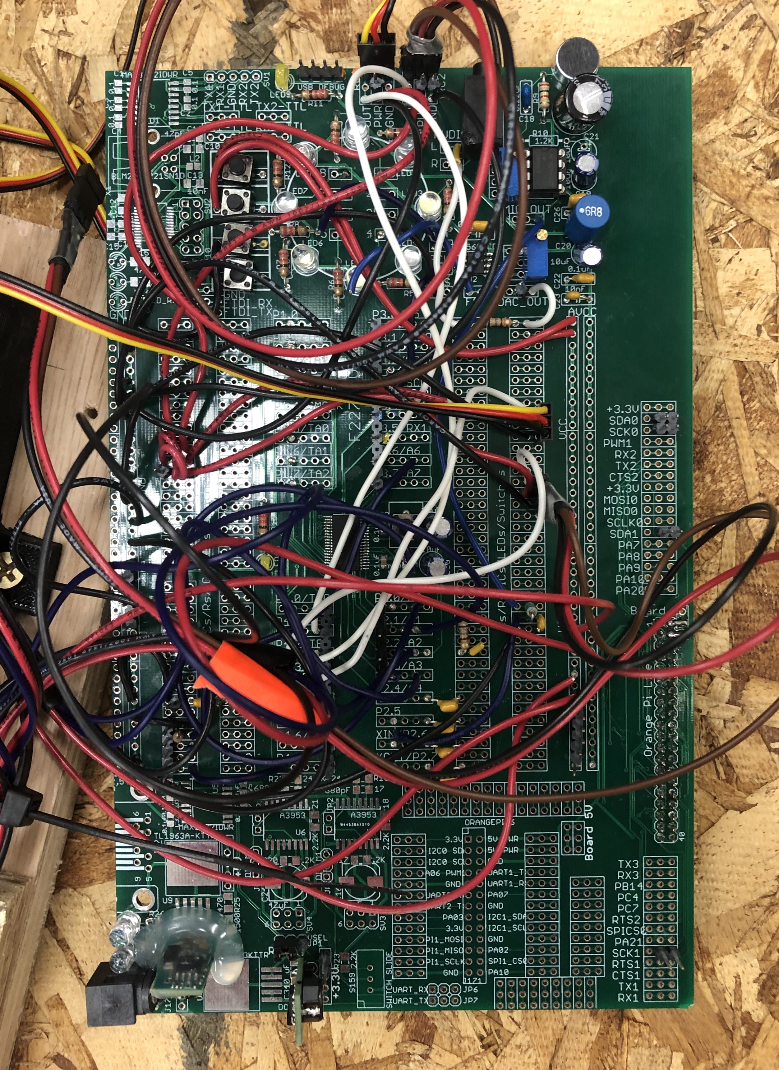
After compiling and fine-tuning the software for this project, a few issues arose with component assembly and constraint. One of the first issues to tackle was the wire lengths on the stock servo motors used as well as the wire lengths connecting the photoresistors. The three-wire ribbon attached to the motors was fairly short and made it difficult to position all of the motors around the iPad without the board being pulled from multiple directions. To tackle this, extension cords were soldered together with each wire shrink tubed to avoid shorting. These served as a critical component to our functional final assembly. An image of one end of one of these extension cords is shown below in Figure 5. Similar soldering was done to extend the wires connecting to the photoresistors.
Another pain point was the constraint of the motors and photoresistors around the iPad itself. The motors had to be held rigidly in place against the reaction forces caused by the styluses tapping the screen with enough force to register touch. To combat this, the aforementioned PLA 3D printed casing was designed with 8 holes around each motor's location for zip ties to be strapped around the motors in multiple key places. For the photoresistors, the acrylic piece shown resting on top of the iPad screen was designed with four holes to place the photoresistors into. Hot glue was applied on top of the photoresistors to hold them down against any pulling forces from the wires. These custom components can be seen serving their respective functions below, in a video of the Tile Tapper in action.
ConclusionIn working on this project, Team M&P430 explored how the MSP430 can be applied to a wide range of projects, from hobby electronics to real-world technology. This project pushed the processor to its limit, balancing processing power and speed to accomplish the tile-tapping goal it was designed to achieve.
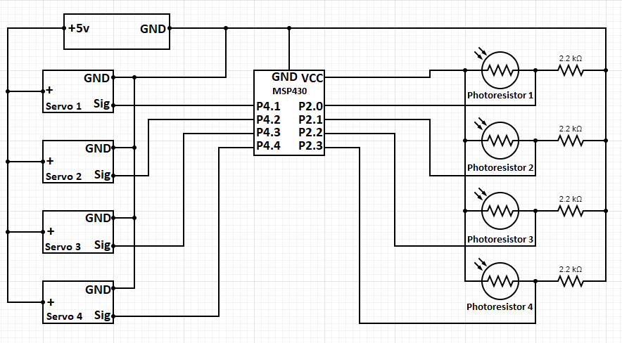
Circuit Diagram


Comments