

Hardware components | ||||||
 |
| × | 1 | |||
| × | 1 | ||||
 |
| × | 1 | |||
 |
| × | 1 | |||
 |
| × | 2 | |||
| × | 1 | ||||
| × | 1 | ||||
| × | 1 | ||||
 |
| × | 1 | |||
 |
| × | 1 | |||
 |
| × | 2 | |||
 |
| × | 1 | |||
 |
| × | 1 | |||
| × | 1 | ||||
Software apps and online services | ||||||
 |
| |||||
Hand tools and fabrication machines | ||||||
| ||||||
 |
| |||||
 |
| |||||
 |
| |||||
My daughter loves sweets. She loves them so much that she would do anything to get them: skip meals, steal them from the secret hiding places, she's even willing to be punished if caught doing that, as long as she gets her sugar dose.
Sugar activates the brain's reward system. Activation of this system leads to intense feelings of reward that can result in cravings and addiction. So drugs and sugar both activate the same reward system in the brain, causing the release of dopamine.
We all use Fitbit fitness trackers in our family, but her stepping isn't that great. But what if we sync her desire for sweets with her actual daily activity? What if I can make her add physical activity in order to get these rewards? I guess that would be ok, since, I don't have a problem with sweets in general, but I have a problem with eating sweets while getting fat on a couch. :)
So, checked their API and saw that they expose the daily activity indicators like steps, floors climbed, distance, calories, etc. The only thing left to do was a candy dispenser able to give her candies based on her activity level. And to make things more fun, I decided to add the entire family in this competition and make this dispenser multi-user capable. This opens the gate of some fun family challenges with sugary rewards involved.
The project is fairly simple. The trickier part is not the electronics, if you are familiar with the basic concepts, but the mechanical part.
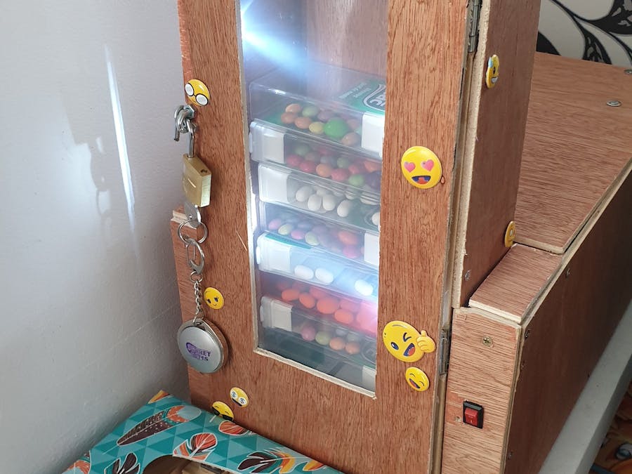
- The candies are arranged vertically inside a tower-like box
- The micro-controller, an ESP8266 NodeMCU sets up a HTTP server listening for connections on LAN.
- A companion web app which can be hosted on the internet, sends and receives HTTP messages to dispense candies or get status information.
- The companion app can have any logic but my version gives you candies based on the fitness activity you do with Fitbit. You can easily write a different logic since the dispenser itself can be controlled using a Restful API. Like give you candies when you receive a like on facebook :) Go nuts!
- If a candy is requested through the API, the micro-controller instructs a servo-motor to move, which in turn makes a tray slide, finally pushing a candy out
- The device is pretty basic. Extras include lighting and playing a silly melody with a buzzer at the end.
- Because the machine is a dispenser, there is only one main command dispense
- When the micro-controller receives the dispense command, it will make use of a 360 degree continuous servo to complete this job.
- The servo is pushing a tray forward and can pull it back though a push-pull-rod,
- The tray is sliding on tracks. You can easily made tracks from two stiff metallic rods. Lubricate the rods to improve sliding and minimize unpleasant noise. The tray can be made out of wood, plastic or even metal. I suggest you make the tray as thin is possible, yet able to move the candy out, and mount the tray as close as possible to the ground,, preferably not touching the ground. This will help prevent jams due to the smaller angle in which the candies are falling.
- The tray is initially sitting inside the tower on the very bottom with all candies on top.
- First, the servo-motor pulls back the tray to make room for the next candy, The next candy drops on the bottom of the enclosure, while the tray retracts, then the tray is pushed forward, which in turn pushes the candy outside.
- There are two metallic sensors, one in the front, one in the back, which can tell when the tray arrives on the final or initial position. They act like push buttons and are handled using interrupts, for increased safety and responsiveness.
- A software jam-protection was implemented to prevent damage, if the tray does not arrive at destination in the expected time-frame (set to 1 sec)
- For maintenance, there are commands for moving the tray back and forward, but you can just move the tray with your hand if it gets stuck :).
Notes:
Using a different type of motor can work too. I had a continuous servo, but I guess a positional servo or even a stepper motor or a plain DC motor will work. If you rely on their fixed positioning accuracy, you can even ditch the initial/final position sensors. One issue with removing those could be position calibration and manual changes in the shaft position.
You need to make the servo horn longer; For this you can attach a 7-8 cm plywood extension like I did, with screws. The control rod typically has a z-bend (a bending in the shape of the letter Z) in the end connected with the horn, and a 90 degree bend with a spring retainer on the other end. My Z Bend wasn't too great, because I used a very rigid wire and didn't had the right tools, so I actually used a U bend which works pretty good. The idea is that the rod should not escape from the horn. It's a nice addition to make sure the hole where the rod moves does not wear out (especially if the horn material is softer like wood or plastic), so I inserted a rubber gasket. To make the spring retainer you can use some springy wire and a piece of heat shrinking tube.
Don't forget to secure the horn to the servo with the provided screw. You might need to drill a hole in the wooden extension so that the screw is actually attached to the plastic horn.
All ESP8266 based boards have a built in regulator, so you can just connect an USB cable, which will feed 5V, and the built in regulator will provide the chip with 3.3V. Note that the servo is connected to the 5V input, because it needs more power. So basically the input voltage is 5 volts and the device will need up to 1.5A when dispensing. When not dispensing, the WiFi chip typically consumes 50 - 300 mA, and the LEDs 30mA each. I didn't implemented a power saving mode, but in standby, it should not exceed 120 mA.
LightingAny cool dispenser has a transparent panel for you to check out the treats inside, complemented with lighting.
I didn't go too far with the lighting, even if you go nuts with colorful LEDs. I just used two white LEDs for the front panel, activated by a NPN transistor. The front panel lights serve as status & error indicator too.
When the device connects to WiFi the lights fade in and out slowly until the connection is established, when the lights lit to a higher intensity. I am just using a PWM pin to control the intensity of the light.
The circuit is a standard low side NPN switch.
If you are a beginner, read on
It is a called a low side switch because the transistor is switching the path to ground. The load's VCC input is connected directly to the power source positive output, while the ground of the load is connected through the transistor, attached to the collector pin. If enough voltage and current is applied to the base of the transistor, the transistor gets saturated and conducts from collector to emitter.The load consists out of our two white LEDs, with the positive (anode) connected through a series resistor, to limit current.To activate the "switch" we send a logic 1 to the transistor's base, through a series resistor. A transistor without a resistor on the base is like an LED with no current-limiting resistor. The value of the resistor, and voltage across it, will set the current. The resistor needs to be large enough to effectively limit the current, but small enough to feed the base enough current. You can calculate this value based on your transistor and load. For example, my NPN3904, having a hFE=100 works well with a 5k resistor to switch 60mA,, so I used.a 4.7K one, which should handle 70mA at 3.3V with a forward LED voltage of 3.3V. I used a very small 1.8 ohm resistor for limiting the LED current, since the forward voltage of the LED should be the same, and the voltage is regulated. You can use this calculator for base resistor. and this one for LED resistor.Safety & candy-theft protection
To prevent unauthorized access to the candies (basically to prevent my daughter stealing candies :) ) I used a plain old lock. I think this issue cannot be overlooked if you want to avoid cheating :)
SoundFXI am using a passive buzzer to play a melody once the dispensing process is completed. Since playing a melody is usually done with delays, I created a safeDelay function to delay at smaller increments (100ms) to let the internal ESP8266 processes run more frequently, Delays are considered a bad practice, but the melody is played at the very end of the dispensing process, so it should not affect the ability to respond to useful commands.
The enclosure was built using plywood. The front door has a transparent plastic panel to see the treats inside.
The most important aspect is sizing the candy tower. I built the tower for the dimensions of a jumbo Tic-Tac box. This convenient plastic box has a small living hinge lid and can fit small candies like M&Ms, Smarties or similar, and by removing the cap completely you can put chocolate pieces like Kinder bars or anything that fits. The candy tower should fit the Tic-Tac box quite tightly, with only a few millimeters spacing in all directions. If there is too much or too less room, the Tic-tacs will jam,
It is very useful to add a lid or a door to the enclosure, so you can do maintenance. Maintenance can include lubricating the rails. In my version, there is no way to get a candy out by opening the lid, so there is no point in securing it.
A nice addition is also a power switch. You can just cut the USB cable and attach a small switch to the positive side.
Web AppThe companion web app is written in PHP/Javascript. I actually integrated this feature in a more complex app that I am using for logging food into Fitbit, connected with my DIY Healtzuilla scale.
As a high level overview, the app talks to the dispenser using the assigned LAN IP by HTTP. It uses the status and dispense endpoints to provide candies if the defined challenges are completed. To check if and how a challenge was completed, it connects to the Fitbit Web API using OAuth2 authentication and retrieves the daily stats. It keeps track of the already dispensed (eaten) candies and gives you new candies if you have earned them. It keeps separate stats for different users.
It would be a bit hard to extract the PHP source code related to Dulciurilla from this larger codebase, but with enough requests, I can do a little effort.
Sample ES6 Javascript class for the dispenser using jquery:
class DispenserApi {
    constructor(baseUrl) {
        this.baseUrl = baseUrl;
    }

    executeCall(endpoint, method = 'GET', body = null) {
        return $.ajax({
            type: method,
            url: this.baseUrl + endpoint,
            dataType: 'json',
            data: body
        }).fail(function (jqXHR, textStatus, errorThrown) {
            console.log('Request failed: ' + jqXHR.status);
        });
    }

    getStatus() {
        return this.executeCall('dispenser/status');
    }

    dispense() {
        return this.executeCall('dispenser/dispense', 'POST');
    }
}
It can be instantiated and used like this:
// replace with your dispenser IP
var dispenser = new DispenserApi('http://192.168.0.152/api/');

dispenser.dispense().done(function (dispenseData) {
    console.log("Success");
}).fail(function (jqXHR, textStatus, errorThrown) {
    console.log("Failed");
});The RESTful HTTP API is available at http://<dispenser-IP>/api/. All responses are in json format.
Successful POST/PATCH actions return HTTP status code 200 and a JSON like this:
{"success": true}Failed requests return a non-200 HTTP status code and a JSON object with two keys:
- error: bool (always true)
- message: string (optional)
Example:
{"error": "true", "message": "Something went wrong"}All paths bellow are relative to the scale IP address.
Dispenser API
Ask to dispense a candy
POST /api/dispenser/dispense
Get device status
GET /api/dispenser/status
The device can be in one of these statuses:
- Initializing (code 0) - not ready yet for commands
- Idle (code 1) - ready for commands
- Dispensing (code 2) - in the middle of a dispensing process, New commands cannot be processed at this time
- Error (code 3) - If tray jammed, WiFi not connected.No commands can be processed.
Sample response:
{"statusCode": 2, "statusText": "Dispensing"}Maintenance API
Move tray forward
POST /api/dispenser/maintenance/tray/move-forward
Move tray backwards
POST /api/dispenser/maintenance/tray/move-backwards
Get tray status
GET /api/dispenser/maintenance/tray/status
The tray can be in one of these statuses:
- Stopped (code 0)
- Moving backwards (code 1)
- Moving forward (code 2)
Sample response:
{"status": 1, "statusText": "Moving backwards", "operationTime": 360}


_3u05Tpwasz.png?auto=compress%2Cformat&w=40&h=40&fit=fillmax&bg=fff&dpr=2)
Comments