


Hardware components | ||||||
| × | 1 | ||||
| × | 1 | ||||
| × | 1 | ||||
| × | 1 | ||||
| × | 1 | ||||
 |
| × | 1 | |||
_ztBMuBhMHo.jpg?auto=compress%2Cformat&w=48&h=48&fit=fill&bg=ffffff) |
| × | 1 | |||
 |
| × | 1 | |||
 |
| × | 1 | |||
Software apps and online services | ||||||
 |
| |||||
I've recently posted a tutorial about this project on YouTube explaining everything you can read on this article. You can watch it right below.
IntroductionIn this lesson, we’re stepping into the world of input and output modules - starting with one of the simplest but most powerful: the push button.
We’ll learn how to use buttons to control LEDs, buzzers, and other components. And we’ll update the ultrasonic alarm we built in lesson #6 to make it smarter - with a manual reset feature that gives you full control over how the system behaves.
This is lesson #7 of a 24-part series called Arduino for Beginners. If you haven’t checked out the earlier lessons, I highly recommend starting from the beginning, since each class builds on the last one.
You can read the articles of this course or watch the related videos on this YouTube playlist.
Sounds good? So let’s get started.
SponsorAll components I'll use for the project come with the MindPlus Arduino Coding Kit - a complete kit provided by DFRobot that contains everything you need to take your first steps in the Arduino world.
It comes with a wide range of components: sensors, cables, modules, an Arduino UNO, an LCD screen, and more. We’ll be using every single item in this kit throughout the 24 lessons in this course.
My kit was generously provided by DFRobot, the sponsor of this series.
If you haven’t heard of them, DFRobot is one of the leading companies in open-source hardware. Their online store is packed with high-quality components and kits - not just this one, but many others as well. And the best part? They ship worldwide through a network of trusted partners.
So, if you're planning your next STEM project, I highly recommend checking out DFRobot. You’ll likely find exactly what you need.
If you take a closer look at your MindPlus Arduino Coding Kit, you’ll spot a small yellow module with a button on it. Go ahead and grab it - we’ll be using it in this lesson.
This isn’t just any button, it’s called a push button. What makes it special is that its internal contacts only touch when you press it. As soon as you release the button, the contacts separate and the circuit is opened.
So, when you press the button, the contacts close and electricity flows through. Release it, and the flow stops. Simple enough, right?
Now, how do we actually use this button with Arduino?
If you've followed along with the previous lessons, you might be thinking, “we just connect it to a digital port set as input.” And you're almost right!
But if you try that, just setting the port to input and connecting the button, you’ll probably notice something odd. The port might randomly switch between HIGH and LOW, even when you’re not touching the button. Weird, right?
This happens because of electrical noise or electromagnetic interference from the board itself. Basically, without a clear signal, the input "floats" and picks up random voltage changes.
To fix this, we need a resistor that forces the port into a known state - either HIGH or LOW - when the button isn’t being pressed. This is called a pull-up or pull-down resistor. When the button is pressed, it forces the opposite state.
In our case, since we’re using a crowtail button module and can’t easily add an external resistor, we’ll set up the Arduino’s built-in pull-up resistor. That means the input pin will naturally read HIGH. But when we press the button, it changes to LOW. This way, we can reliably detect when the button is pressed.
And in our example, we’ll use that button press to reboot the alarm system.
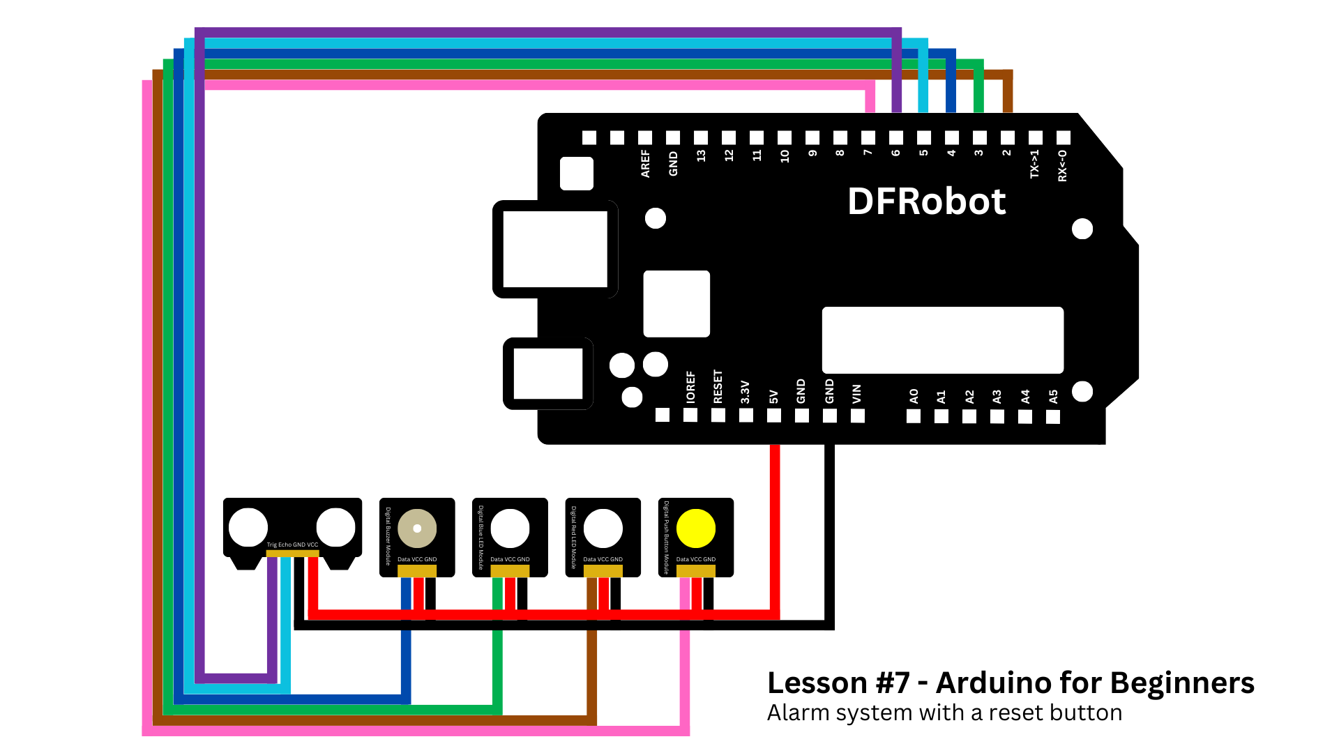
ProjectToday's project is basically the same one of the last class but with a difference. We'll connect a button to port 7.
If you didn't watch lesson 6, don't worry. Here's the list of materials we are using:
- DFRobot MindPlus Arduino Coding Kit
- 1 x DFRobot I/O Expansion Shield
- 1 x DFRobot Digital Buzzer (active buzzer)
- 1 x DFRobot Digital Piranha LED Module - Red
- 1 x DFRobot Digital piranha LED module - Blue
- 1 x DFRobot Digital Push Button
- 1 x Arduino UNO
- 1 x Ultrasonic Sensor (generic)
- 1 x Jumper wires (generic)
You can refer to the schematics below, so you know exactly how to connect everything.
Now let's take a look at the code. As you can see on the images below, it's the sketch of lesson 6 with some changes.
By the way,this script is available on the GitHub repository of this series.
To make our alarm system smarter, we’ve added a push button to pin 7 of the Arduino board.
const int buttonPin = 7;This button gives the user the ability to manually reset the alarm while it's active.
Inside the setup() function, we’ve configured this pin using INPUT_PULLUP.
pinMode(buttonPin, INPUT_PULLUP);This tells the Arduino to use its internal pull-up resistor, so we don’t need to add an external one. When the button is not pressed, it reads HIGH. When the button is pressed, it reads LOW.
Now let’s look at how the alarm works.
When an object gets closer than 10 centimeters, the triggerAlarm() function activates.
if (distance > 0 && distance <= 10) {
  triggerAlarm();
}
It starts blinking the LEDs and sounding the buzzer for up to 30 seconds.
void triggerAlarm() {
  unsigned long startTime = millis();
  while (millis() - startTime < timeWorking) {
    digitalWrite(redLED, HIGH);
    digitalWrite(blueLED, LOW);
    digitalWrite(buzzer, HIGH);
    delay(250);
    digitalWrite(redLED, LOW);
    digitalWrite(blueLED, HIGH);
    delay(250);

    if (digitalRead(buttonPin) == HIGH) {
      break;
    }
  }

  digitalWrite(redLED, LOW);
  digitalWrite(blueLED, LOW);
  digitalWrite(buzzer, LOW);
}
But here’s the key part: during those 30 seconds, the Arduino continuously checks if the user has pressed the button.
if (digitalRead(buttonPin) == HIGH) {
  break;
}
If the button is pressed at any time during the alarm, the loop immediately breaks, and the alarm turns off.
If the user doesn't press the button, the alarm will stop automatically after 30 seconds.
In both cases, after the alarm ends, the system turns off all LEDs and the buzzer - and resumes monitoring again.
This creates a responsive system where the user can quickly silence the alarm if needed, without waiting for the full 30 seconds.
Now let's upload the code and see it working.
Mind+This time we won't be using Mind+, as we did in the previous lessons, because unfortunetely, it doesn't have a block code that definies the pin mode (input, output, or input pull-up).
But you can use it to write code in C (similar to what we've done on the Arduino IDE) if you want to.
ConclusionThis is the end of lesson 7.
You built your first project that uses both input and output modules working together.
You learned:
- how push buttons work
- how to read their signals
- how pull-up resistors help make those readings stable
And most importantly, you learned how to create more interactive systems. We'll use this knowledge to create more complex projects later.
In the next lesson, we'll learn about the serial monitor - an important tool for debugging and a topic every maker should understand.
Thank you so much for reading this article, and I’ll see you in the next one.


Comments