


Hardware components | ||||||
 |
| × | 1 | |||
 |
| × | 1 | |||
| × | 1 | ||||
 |
| × | 1 | |||
 |
| × | 1 | |||
| × | 1 | ||||
| × | 1 | ||||
| × | 1 | ||||
 |
| × | 1 | |||
 |
| × | 1 | |||
 |
| × | 1 | |||
| × | 1 | ||||
| × | 1 | ||||
 |
| × | 1 | |||
| × | 1 | ||||
Hand tools and fabrication machines | ||||||
 |
| |||||
 |
| |||||
One of the very first times I ever watched a movie is when I binged the entire prequel Star Wars saga with a bunch of friends. At the time, we fantasized about having our own lightsaber battles, to the point where we all begged our parents to get cheap plastic knock offs for $20 at a local game store. We would battle for hours with these lightsabers, to the point that several of them broke and needed replacing. 10 years later, and I was finally presented with the chance to make my own lightsaber, entirely from scratch, however I wanted. So, along with my friend Mustafa, I decided that this would probably be my last realistic chance to do something so creative and fun, especially given that I'm a finance major, while he's pre-med.
Since we had practically no previous electrical engineering experience, along with almost no coding experience as well, we knew we had a long path ahead of us. So, to move the process along, we decided to split the tasks needed to build the lightsaber. While he worked on making the lights of the lightsaber, as well as the button, I would focus on making the sound system, as well as a motion system that would ideally integrate with both the sounds and lights. Ideally in the future, I would also like to add touchscreen functionality to have more control over the lightsaber (startup sequences, volume control, precise light control). That way, we would be able to (hopefully) have fully functioning lightsabers to battle with.
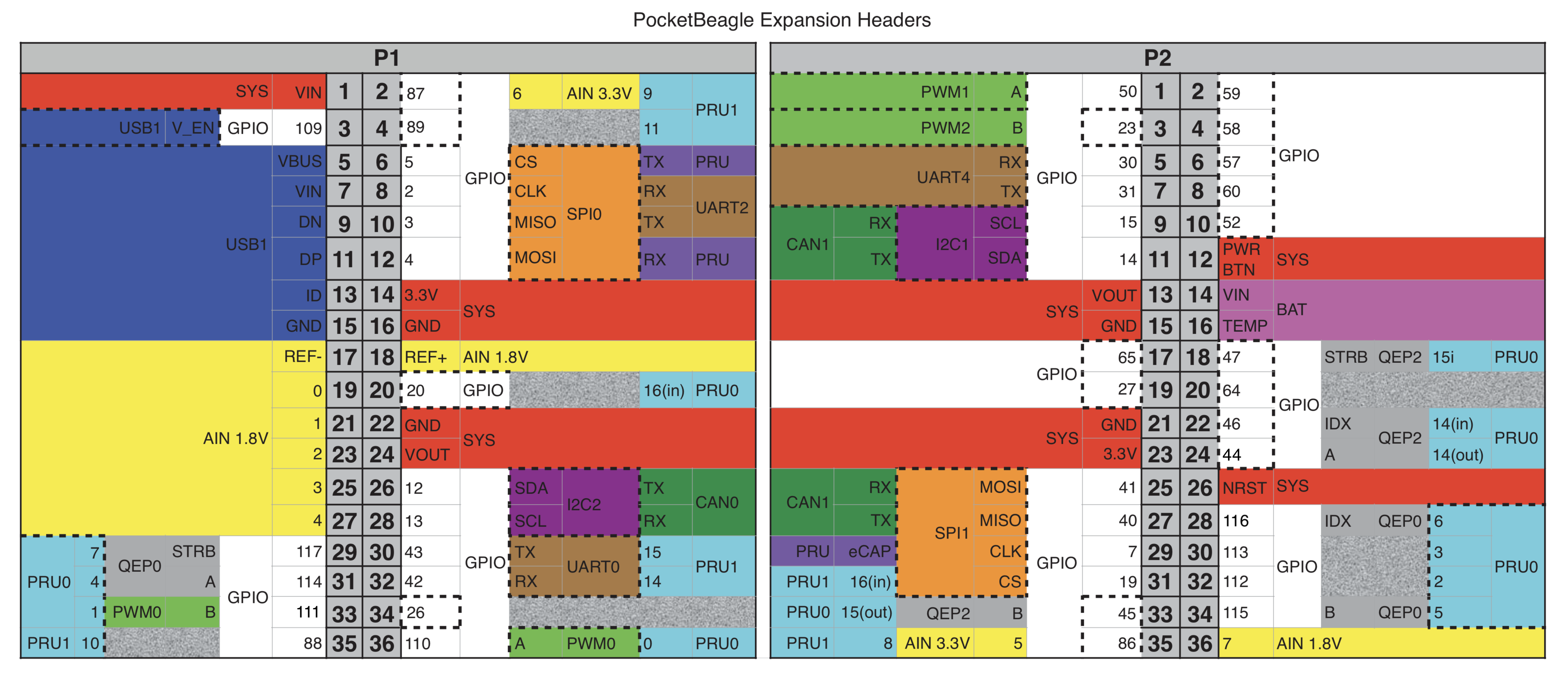
PocketBeagle PinoutAs we are using a PocketBeagle, I will often be referencing this table and the pin layout for wiring purposes.
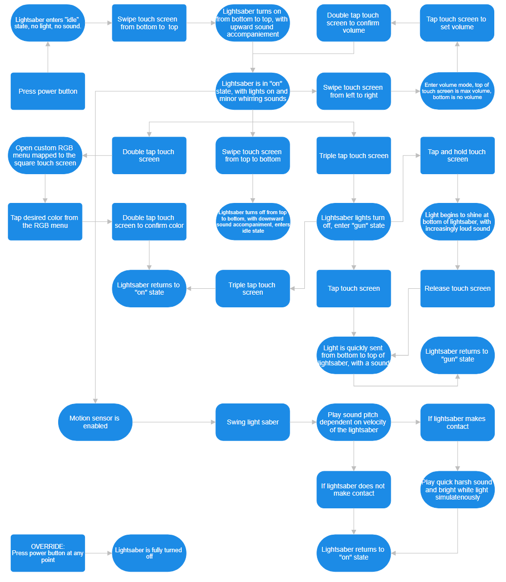
What does the lightsaber do?This software block diagram encapsulates, ideally, all of the functionality of the lightsaber.
Once the power button on the PocketBeagle is pressed using an external button, the lightsaber enters an idle mode, waiting for feedback from the user. Swiping up from the bottom initiates the lightsaber boot up sequence, and switches the lightsaber to its "on" state. While the lightsaber is in its "on" state, an IMU sensor is used to track the acceleration of the lightsaber. This makes it so that the lightsaber plays certain audio dependent on the velocity of the lightsaber swing. Additionally, it means that its able to detect contact, playing a "clashing" sound upon contact, and quickly flashing white, before reverting to its normal color.
From the "on" state, there are several options for the user to choose from.
By double tapping the screen, the user will be able to access any color on a square color picker represented by the touch screen. As they either drag or tap on the screen, the lightsaber will light up with its corresponding color. Then, the user can double tap again to confirm the color choice.
By triple tapping the screen, the user is able to access a perhaps unorthodox version of a lightsaber; the gun-saber. Referred to as the "gun" state, the user can either choose to tap the screen to briefly emit a quick burst of light stating from the hilt and bursting upwards, or can choose to "charge" a blast by holding the touch screen, and "shooting" the blast by releasing the touch screen. The user can revert back to the standard "on" mode by once again triple tapping.
By swiping from left to right, the user is able to access volume control. Here, the top of the touch screen indicates max volume, while the bottom indicates minimum volume. This serves as a master volume control panel, meaning that all background humming, lightsaber swinging and lightsaber clashing is dependent on this master volume. The user can then double tap to confirm the volume setting.
Finally, if the user is done with the lightsaber, they can swipe down from the top to initiate the deactivation sequence. However, it's important to note that when the lightsaber is deactivated, it is still in the idle state, not the off state. This means that swiping up from the bottom will reactive the lightsaber once more. The only way to fully turn off the lightsaber is by pressing the master power button to turn off the PocketBeagle entirely. The user should always seek to deactivate the lightsaber before fully turning it off, as they run a risk of having a bad startup if the lightsaber is turned off during its "on" state.
Currently, due to hardware limitations, the lightsaber uses a more simple method, with only a button being used. Holding down the button activates it to its "on" state. Clicking the button cycles through a predetermined set of colors, and holding the button back down deactivates the lightsaber.
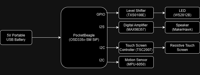
Build InstructionsOnce we understand what we want the lightsaber to do, we can begin the construction process. Here is a system block diagram denoting how the hardware will be connected:
First and foremost, the PocketBeagle is the most essential piece of hardware for this project, as everything runs through it. For programming purposes, it connects via MicroUSB to a laptop to download code onto a microSD card.
Power
When running as a standalone project without a computer, an external source of power must be supplied. We are currently unable to power the entire project using only the 5V battery due to a combination of software and hardware issues, although we have come up with a solution for when everything is integrated. To connect the portable battery, attach a jumper wire (black) from the first pin to the negative power rail, and a jumper wire (white) from the fourth pin to the positive power rail. This battery pack serves as the power source for our 5V components.
When powering our components with aid of a computer, the following setup is used to power our 3.3V components. Attach a jumper wire (black) from P1_16 to the other negative rail, and attach a jumper wire (white) from P1_14 to the other positive rail. Now, we have power for all of our components.
Button
Under a temporary system for the lightsaber until the touchscreen is fully implemented, a button is being used instead. This button serves to activate, deactivate, and change colors of the lightsaber. To properly connect the button, a 1kΩ resistor is attached on the top row of the button's connection to the positive side of the 3.3V rail, and a small wire is connected from the bottom row of the button's connection to the negative side of the 3.3V rail. Additionally, a jumper wire (blue) is attached from the top row to the GPIO pin P2_04.
LevelShifter
To have each component of the lightsaber be supplied with the proper voltage while connected, we need to use a level shifter. The level shifter used (TXS0108E) should have its "A" side on the 3.3V side of the breadboard, and the "B" side on the 5V side. VA should connect to the positive 3.3V rail (brown), while VB should connect to the positive 5V rail (grey). VA and OE are connected (blue) to ensure that any point across the level shifter can be used as an access point for power, while GND connects to all grounds (green) by connecting the A and B side of the level shifter through the middle wire (brown), while simultaneously being connected to the negative 3.3V rail (grey) and the negative 5V rail (brown). To connect the level shifter to the PocketBeagle using a jumper wire, connect A1 to P1_08, with pin P1_08 configured as GPIO.
IMU
The MPU-6050 is an IMU sensor combining a gyroscope and an accelerometer to detect changes in motion. By using a combination of the gyroscopic and acceleration readings, we are able to calculate overall movement of the lightsaber, letting us set certain thresholds for hit detection. These readings are incorporated into the light and sound aspects of our lightsaber to provide a fully immersive experience.
The IMU connects its VCC to the positive 3.3V rail (red) and the GND to any ground, in this case using the level shifter's extended ground row (orange).
To connect with the PocketBeagle, the SCL is connected to P1_28 (green), and the SDA is connected to P1_26 (yellow). These pins both need to be configured to I2C for functionality.
DigitalAmplifier/Speaker
The MAX98357A is a digital amplifier used to connect an external speaker to the PocketBeagle. However, to get these two components connected, the small protruding green piece pictured must be soldered onto the amplifier so that the require connections for the speaker exist. To connect the speaker to the amplifier, connect the red wire to the positive end, and the black wire to the negative end. To give power to the amplifier, connect Vin to the positive 5V rail (grey) and GND to the negative 5V rail (brown). Meanwhile, to connect the amplifier to the PocketBeagle, connect LRC to P1_33 (brown), BCLK to P1_36 (red), and LRC to P1_33 (orange).
The digital amplifier/speaker setup is currently not operational due to problems with integrating I2S with the PocketBeagle. Due to several overlays running at once, configuring I2S pins without crashing the PocketBeagle has proven to be extremely difficult, although we hope to eventually solve these issues.
LEDStrip
The LED strip acts as the light source for the light saber. Upon lightsaber activation, the LEDs will light up one by one from the bottom to the top to emulate a real lightsaber turning on. The LEDs will then cycle through various colors dependent on user input, until eventually being turned off the opposite way it was turned on.
Eventually, we plan on having full integration with contact (IMU sensors), as well as personally achieving the "gun" state I mentioned previously. However, so long as the touch screen doesn't work, integration will continue to allude us.
The LEDs are connected to the level shifter as follows: The white wire, serving as the ground, is attached to the ground of the level shifter (grey). The green wire, serving as data relay, is connected to B1 (white). The red wire, serving as the power input, is connected to VB (black). This color scheme is counter intuitive, so please feel free to choose other methods of connecting these wires.
CompletedDesign
All told, the completed design at this stage looks like this:
While this prototype is only able to integrate the IMU, button and lights, we have a lot of the framework down for the speakers to eventually be able to create a fully fledged lightsaber once the fundamental I2S configuration problem is resolved. As of now, the touch screen remains a work-in-progress, with total integration between speakers, lights and IMU the current issue to solve.
WieldingtheLightsaber
When completed, the lightsaber currently, turns on, off, and can cycle through various colors. Unfortunately, we do not currently have the housing or hilt to make our prototype a true lightsaber replica, although it glows significantly more now than it will when it's put inside of a casing. In the video, I demonstrate the lightsaber turning on, flickering through various colors, and then turning off.


_3u05Tpwasz.png?auto=compress%2Cformat&w=40&h=40&fit=fillmax&bg=fff&dpr=2)


Comments