


Hardware components | ||||||
 |
| × | 1 | |||
 |
| × | 5 | |||
 |
| × | 2 | |||
 |
| × | 1 | |||
 |
| × | 1 | |||
Software apps and online services | ||||||
 |
| |||||
Hand tools and fabrication machines | ||||||
 |
| |||||
 |
| |||||
 |
| |||||
 |
| |||||
 |
| |||||
PROBLEMS
SOLUTIONS
FUNCTIONS
AUTOMATIC
MANUAL
COLOR CODE BREAKDOWN
MANUAL
AUTOMATIC
POSSIBLE ISSUES
DESIGN DEVELOPEMENT
NOTES ON LASERING
NOTES ON SIDE PANELS
CONCLUSIONS
FUTURE SETUP
I had two main reasons for creating this site-specific piece. The first was to aid in LEAN inspired communication for both teacher and students. The second was to provide a learning tool that familiarizes students with their microcontrollers in the Internet of Things classroom.
Due to the intense and condensed nature of the course material, there is likely to be inefficiency caused by disparate levels among individual learners. Vygotsky’s theory, the zone of proximal development, diagrams the points where students are able to complete tasks on their own and where they no longer are able to based on lack of knowledge. Because this zone is different for all students, it presents a significant challenge for instructors to match individual needs in a classroom.
Image credit: helpfulprofessor.com
Additionally, some learners struggle to voice their needs (or even know what they are), may not ask for enough help, or may ask at inappropriate times when teachers are helping other students or busy with other tasks.
SOLUTIONSMy solution is the Practical Particle Photon YOU, a tool for classroom comprehension checking and LEAN communication.
Inspired by the IoT micro control chip, the Particle Photon 2, it implements a color code system to communicate with users. This gives teachers a quick visual read (visualRead in code), on the state of their class. They can in essence perform a sort of triage, grouping students for additional clarification or providing specialized attention to individuals.
According to LEAN principles, a visual cue cuts down on excess noise and gives students (or workers) additional ways to ask for help. Improved communication cuts down on wait time and provides measurable feedback for improvements to be made.
FUNCTIONSAUTOMATIC: At rest, neo pixel strips will glow a colorful rainbow and an OLED screen will provide the current number of the IOT cohort (in this case #14). Ideally, a motion sensor would be installed to prompt action by passers by. Currently, there is a BME device sensing room temperature. When the temperature falls below 75 degrees, a message is activated indicating that the room is possibly too cold for sedentary bodies. WEMO devices will be activated to signal those seated that they should move around to get their blood flowing. Those who are lucky enough to be seated next to lava lamps, can warm their fingers.
MANUAL:
Because the weather is getting colder, the additional feature of the Practical Photon YOU will be even more useful. Eventually, it will act as a WEMO controlled device itself. Paired with its smaller companion, the Particle Photon WHO’s There, the Photon YOU will perform the important task of class doorbell.
Every morning, the instructors and students must wait for each other at the front door of FUSE. Slack has proved to sometimes fall through, so another way of getting attention will benefit all.
The Photon YOU will be equipped with an MP3 controller and a doorbell track. The Photon WHO will be placed on glass front door by means of a suction cup or magnets on the metal frame. When pushed, the button will activate the device inside the classroom through sound, as well as flashing the HUE lights in the room white, to indicate there are students waiting locally.
Echoing the HUE lights, the Photon YOU neo pixels will glow white to indicate local waiting and will start to flash if the button is pressed again. An extra stretch, stretch goal would be to turn the device into an intercom.
In future iterations, remote functionality will be extended to Photon WHO’s stationed at each table (someday, for each student). Students will be able to use the remote devices to indicate their understanding or mental state in reference to class material or tasks.
COLOR CODE BREAKDOWN
The Photon 2s use colors and flashing speeds to indicate their mode/task to the user. When flashing, a rapid series of colors follow each other, starting from white, usually moving to green or blue to indicate internet connectivity and yellow to indicate that the input is being transferred. Occasionally, it is necessary to manually reset using the mode and reset buttons. A magenta light flashes to indicate this process is beginning. If the microcontroller ever flashes red, there is a strong chance that something has gone very wrong.
Using the communication system already in place, each table (and eventually students), will be able to cycle through a selection of 7 colors (white will be automatically activated once the doorbell is rung).
Currently, there are 5 neo pixel strips, one for each table. The MODE button cycles through each table and the RESET button cycles through the colors on each strip. This is not functioning as of November 4, 2024, my coding ability began as limited and subsequent mental demands made even rudimentary tasks seem enormously complicated.
The colors and their meanings follow:
- White - Waiting locally (arrived to class)
- Cyan - Accessing class materials (IOT folder, GitBash, class slides)
- Blue - Listening mode (need more/new info –may be used during lecture
- Green- Connecting to the internet (searching online/researching/brainstorming independently)
- Yellow- Waiting for input/ uploading (applying teaching by working on assignments/ discussing with classmates)
- Magenta - Updating/reset required (time for questions and clarification from instructors)
- Orange - Trying to connect but failing (tried to apply instructor feedback, but unable to upload i.e. understand/lack of skill or knowledge causing distress)
- Red - SOS, firmware crashing (confused, frustrated and nearing meltdown/fatal error)
MANUAL AND AUTOMATIC
Students and instructor manually use buttons to change between tables and colors. Future remotes are addressed to the tables and only need cycling through colors. The HUE lights at tables will be set to match the neo pixel color that was selected. This may need to be overridden if student privacy is preferable.
POSSIBLE ISSUES
While it is important to give instructors accurate assessments of level of understanding and/or mindset, safeguards may need to be implemented to avoid overuse of help modes, diluting their meaning and urgency.
It would be hoped that the red light never be reached, however, in the high stress environment, it is likely to be used at some point–such as during the midterm and final projects. I personally felt in the Orange Zone for the majority of the week.
Group work and peer feedback in the Yellow Zone should be encouraged and fostered, but during periods when everyone is working on their own projects, this may not be accessible.
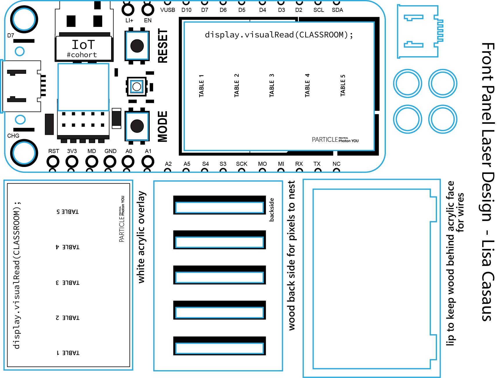
DESIGN DEVELOPMENT
The casing for the device was designed in Adobe Illustrator after extensive measuring of components, including OLED screen, breadboards and buttons. The microcontroller was turned into a vector graphic by tracing the diagram by building up shapes and inputting text. Cuts were planned according to measurements taken.
NOTES ON LASERING
Engraving was done on ¼ thick black acrylic. Two cuts were needed to pass through the acrylic a setting of Speed 8, Power 100, and MHz 5000. Engraving was done at Speed 50, Power 70.\
This was done without protective paper, which I do not recommend. Acrylic paint was applied to the crevasses and wiped away fom the raised surfaces to highlight the engraving. However, this was made difficult because the rough texture left behind by the scorching caught the paint instead of wiping clean away. A retarding medium was needed to facilitate cleaning. In future, the tedious step of peeling the protective paper is well worth it.
NOTES ON SIDE PANELS
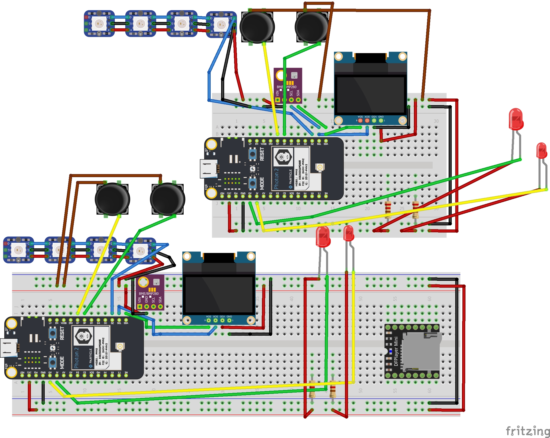
The side panels were designed after a good portion of wiring had been started. It was necessary to see how much space to give the breadboard and wires. There is still some engineering to be done to hold the neo pixels in place and the wired breadboard likewise. They are currently loose or taped into place.
Modeling the side panels after the pin system provides flexibility in addition to making the design functional as a learning aid. The D pins on the left and right are labeled in the back and can easily be seen at the same time when viewed from this vantage point.
At some point, there would ideally be more layers that stack or fold to show the pin classifications and extra capabilities in a three-dimensional model. Each student has the two-dimensional diagram pasted in their notebooks.
However, the diagram is slightly blurry, and text is small, necessitating close inspection. This can be frustrating, especially when it derails one from a task – this was happening to me as I tried to wire and code.
As I worked on the design, this possibility took form to use such devices on the desks for this reason as well as for a remote device to update the instructor’s Photon YOU
Particle Photon WHO’s There
To make the doorbell casing, I cut another Photon 2 panel to fit the smallest breadboard. It currently has a non-functioning button and LED light installed and will need extra measuring and decisions about extra holes.
CONCLUSION
There were many plans that went awry this week. The first, was my initial choice of project: a brain break cuckoo clock. I chose it from a list of possible ideas, as being the most fully fleshed out and after discussing it with several family members. It seemed to have the most universal appeal.
I had wanted to create a comprehension checking device since the first week of the course, since my zone of proximal development has, and continues to be, heavily taxed by the material. The reason I originally passed it by was because it is very specific and the design is not easily applied to other types of classrooms. However after seeing fellow students struggling, it seemed like something we could all use.
I personally value utility as much or even more than aesthetics, and so decided to pivot on Tuesday from my original plans.
The first day had been delayed by unavailable Illustrator licenses and it did not occur to me to go downstairs to work. I spent most of my time that day building a code bank – pieces of code that would likely be useful from previous projects and measuring components. Some attempts at coding and 2d to 3D extrusion of the base were made.
Tuesday, after finishing a mockup started the previous day, I had doubts about the scale and the ability to manipulate the internal are of the clock into correct placement. I also realized that two other classmates were creating clocks. It seemed we could use some variety. I started to undertake plans for the Practical Photon YOU, was granted permission and direction, started, though the coding process was not clear to me.
Soldering the neo pixel strips was a difficult task in itself and took the rest of Tuesday afternoon. I flashed example code and was dismayed to find that only half of the sticks lit up. After some frustrating resoldering and rewiring and use of the multimeter, it became clear that it was the fault of the code and not the wiring.
The vectoring of the design was completed that night. The cutting completed midafternoon on Wednesday.
The rest of the week was overwhelming, especially due to the amount of task switching that was required. LEAN philosophy discourages the use of multitasking and batching tasks. Instead, it promotes “one in, one out,” or in other words, finishing one complete unit at a time.
This was a significant struggle and did not take place. With so many tasks to complete, each one interdepended on each other, it seemed impossible to prioritize, and I jumped between coding, designing, wiring and assembling.
My code is nearly nonexistent, even after multiple versions were created. On Wednesday morning I attempted to use the browser search to write code for the counting lists for the tables. The neo pixels are using old code that I modified very slightly. No action takes place yet.
Using the browser's code proved to be extremely overwhelming, and I believe that was the starting point of a mental block regarding the code. I had gotten the neo pixels and OLED to work using old code, but now even the lighting up of an LED seemed too complicated.
FUTURE SETUP
In future, I will need to begin with this task and ask for guidance multiple times before mental exhaustion sets in. Coding will continue to be a challenge for me due to the linear nature of the though patterns. As an artist, my mind works in circles, collecting seemingly random items together and trying to make sense of them visually and spatially.
Perhaps this is why math has always been a struggle. I remember my high school algebra teacher expounding the importance of graphing lines. I could never see why until this class. Still, unfortunately, the concepts remain abstract and ungrounded. The resistor is blocking the current.
But I will keep trying.Panel Cover Design


Comments