

Hardware components | ||||||
| × | 1 | ||||
 |
| × | 1 | |||
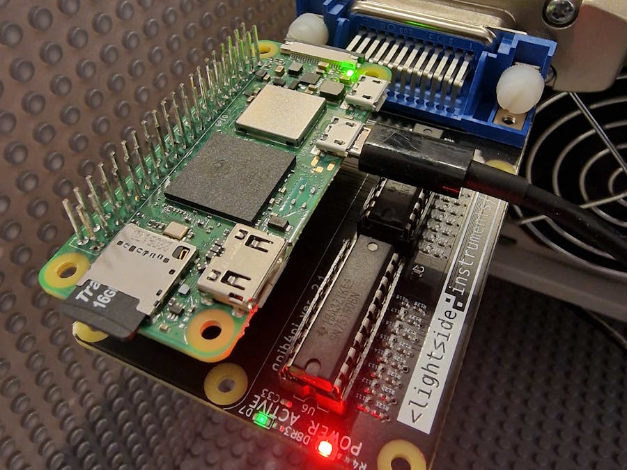
We wanted to manage instruments with GPIB interface from a Raspberry Pi. We also wanted a board that had an opensource KiCAD project that we can modify and produce ourselves when needed.
We decided to base the design on the pinout already supported in the gpib_bitbang.ko driver part of the linux-gpib project and the schematics of a board that supports that pinout - http://elektronomikon.org (if you have one of these boards you can use them too)
However since they did not provide KiCAD design files and BOM for the production of PCB we designed one in KiCAD and published it OSHWA UID: NO000003 (https://github.com/lightside-instruments/gpib4pi) . Feel free to either produce it yourself or buy it on Amazon https://www.amazon.com/dp/B0BY32HH4G or from our webstore - https://lightside-instruments.com/product/gpib4pi
5 improvements to the original elektromikron design:
- Mounting holes for Raspberry Pi Zero form factor control boards
- Pull-up and pull-down SMD resistors matching the IEEE standard values instead of slightly deviating throug-hole arrays present on the elektromikron board
- Complete board design and BOM not only schematic published as certified OSHWA UID: NO000003 project
- The boards purchased after 2024-07-01 have 2x M3.5 stainless steel thumb screws for fastening the board to GPIB ports added to the package. We had to drill the #40-4 original threaded hole part of the Centronix standard to match the GPIB 3.5 mm non-threaded mounting holes.
- There is a stackable 2x20 connector added to the board package that allows connecting the gpib4pi on top of a Raspberry Pi (in addition to Pi Zero that do not need extra offset)
Raspberry Pi5 with 64 bit image https://downloads.raspberrypi.com/raspios_lite_arm64/images/raspios_lite_arm64-2025-10-02/2025-10-01-raspios-trixie-arm64-lite.img.xz was used but other Pi variants e.g. Pi Zero should also work. Configure internet connectivity. Follow these steps (N.B. if you are using version older than bookworm use 4.3.5-lsi4 instead of 4.3.6-lsi8):
apt-get -y update
apt-get -y upgrade
You might want to restart your device here if the upgrade installed a new kernel version so that it runs this version. This only matters for the last command calling module-assistant to rebuild the modules.
apt-get -y install git rsync
git clone -b debian/4.3.6-lsi8 https://github.com/lightside-instruments/gpib-debian.git gpib
rsync -rav gpib/ gpib_4.3.6
rm -rf gpib_4.3.6/.git
rm -rf gpib_4.3.6/debian
tar -czvf gpib_4.3.6.orig.tar.gz gpib_4.3.6
rm -rf gpib_4.3.6

apt-get -y install devscripts
apt-get -y install dh-python bison flex doxygen docbook-utils docbook-to-man tcl8.6-dev python3-all-dev python3-setuptools debhelper autotools-dev automake
cd gpib
debuild -us -uc
cd ..
ls -1 *.deb
#gpib-modules-source_4.3.6-lsi7_all.deb
#libgpib0_4.3.6-lsi8_armhf.deb
#libgpib0-dbgsym_4.3.6-lsi8_armhf.deb
#libgpib-bin_4.3.6-lsi8_armhf.deb
#libgpib-bin-dbgsym_4.3.6-lsi8_armhf.deb
#libgpib-dev_4.3.6-lsi8_armhf.deb
#libgpib-doc_4.3.6-lsi8_all.deb
#libgpib-perl_4.3.6-lsi8_armhf.deb
#libgpib-perl-dbgsym_4.3.6-lsi8_armhf.deb
#python3-gpib_4.3.6-lsi8_armhf.deb
#python3-gpib-dbgsym_4.3.6-lsi8_armhf.deb

dpkg -i *.deb

apt-get install module-assistant

module-assistant auto-install gpib-modules-source
You will need to create the configuration file. This is the configuration file created for my setup:
root@raspberrypi:~# cat /usr/etc/gpib.conf
interface {
	minor = 0			/* board index, minor = 0 uses /dev/gpib0, minor = 1 uses /dev/gpib1, etc. */
	board_type = "gpib_bitbang"	/* name of the driver */
	name = "gpib0"	/* optional name, allows you to get a board descriptor using ibfind() */
	pad = 0				/* primary address of interface             */
	sad = 0				/* secondary address of interface           */
	timeout = T3s			/* timeout for commands */

	eos = 0x0d	/* EOS Byte, 0xa is newline and 0xd is carriage return */
	set-reos = yes	/* Terminate read if EOS */
	set-bin = no	/* Compare EOS 8-bit */
	set-xeos = no	/* Assert EOI whenever EOS byte is sent */
	set-eot = yes	/* Assert EOI with last byte on writes */

/* settings for boards that lack plug-n-play capability */
	base = 0	/* Base io ADDRESS                  */
	irq  = 0	/* Interrupt request level */
	dma  = 0	/* DMA channel (zero disables)      */

	master = yes	/* interface board is system controller */
}


device {
	minor = 0
        name = "digital-oscilloscope-yokogawa-dl1540l"
        pad = 1
        sad = 0

        eos = 0x0a
        set-reos = no
        set-bin = no
}
device {
	minor = 0
        name = "dc-power-supply-agilent-e3647a"
        pad = 2
        sad = 0

        eos = 0x0a
        set-reos = no
        set-bin = no
}
device {
	minor = 0
        name = "relay-actuator-hp-59306a"
        pad = 3
        sad = 0

        eos = 0x0a
        set-reos = no
        set-bin = no
}
This is the corresponding test setup:
Before loading the module find the gpio offset (this is a recent change which hopefully will not be necessary):
root@raspberrypi:~# cat /sys/kernel/debug/gpio
...
gpiochip0: GPIOs 571-624, parent: platform/1f000d0000.gpio, pinctrl-rp1:
 gpio-571 (ID_SDA              )
 gpio-572 (ID_SCL              )
 gpio-573 (GPIO2               )
 gpio-574 (GPIO3               )
 gpio-575 (GPIO4               |gpib                ) in  hi
 gpio-576 (GPIO5               |gpib                ) out hi
...
In this case the offset is 571 and you need to pass it as gpio_offset=571 parameter when loading the module.
Now you can load the module and load the configuration:
modprobe gpib_bitbang gpio_offset=571
gpib_config
* if you are using the older gpib4pi-1.1 board add the board_id kernel module parameter pin_map=gpib4pi-1.1 value e.g. modprobe gpib_bitbang pin_map=gpib4pi-1.1 gpio_offset=571
At this point you can either use the ibtest and ibterm standard tools or write your own programs.
Writinggpibtest.py:
import time
import gpib

con=gpib.dev(0,3)

gpib.write(con,'A1B23456')
time.sleep(1)
gpib.write(con,'B123456')
Running:
python gpibtest.pyThis connects channel A1 to C1 of the classic HP 59306A Relay Actuator while the remaining C channels are connected to their B counterpart.
Same in C. gpibtest.c:
int main() {
    int dev;
    dev=ibdev(0,3,0,T3s,0,0);
    ibwrt(dev,"A1B23456",8);
    sleep(1);
    ibwrt(dev,"B123456",8);
}
Running:
gcc gpibtest.c -lgpib -o gpibtest
./gpibtest
Here is the script used to produce the video enabling A<->C switch connections for 1, 2 and 3 in a loop.
gpibtest-loop.py:
import gpib
import time

con=gpib.dev(0,3)

gpib.write(con,'B123456')
i=0
while(i<10):
        gpib.write(con,'A1B3')
        time.sleep(0.1)
        gpib.write(con,'A2B1')
        time.sleep(0.1)
        gpib.write(con,'A3B2')
        time.sleep(0.1)
i=i+1For a more complex example we convert the Diode characterization example from the Keysight E364xA Dual Output DC Power Supplies User’s and Service Guide to Python -
diode.py:
import gpib
import time

def cmd(con, cmd):
        result = ""
        gpib.write(con,cmd)

        c = gpib.read(con,2048)
        result=c.decode("utf-8")

        return result


con=gpib.dev(0,2)


reply=cmd(con,'*IDN?\n')
print("Instrument identification string:")
print("    " + reply)

gpib.write(con,'*RST\n')        # Set power-on condition
gpib.write(con,'Current 0.5\n') # Set current limit to 0.5A
gpib.write(con,'Output on\n')   # Turn output on

print("Voltage Current\n\n")

# Step from 0.6 to 0.8 volt in 0.02 step
voltage = 0.6
while(voltage<0.8001):
    voltage = voltage + 0.02
    # Set output voltage
    gpib.write(con,'Volt %f\n'%(voltage))
    time.sleep(0.5)
    # Measure output current
    reply = cmd(con,"Measure:Current?\n")
    current=float(reply)
    print("%.3f %6.4f\n"%(voltage, current))

gpib.write(con,'Output off\n') # Turn output off
Running the program:
pi@raspberrypi:~ $ sudo python diode.py
Instrument identification string:
    Agilent Technologies,E3647A,0,1.7-5.0-1.0

Voltage Current

0.620 -0.0000

0.640 -0.0000

0.660 0.0000

0.680 0.0001

0.700 0.0003

0.720 0.0008

0.740 0.0016

0.760 0.0035

0.780 0.0074

0.800 0.0154

0.820 0.0301

pi@raspberrypi:~ $oscilloscope.py:
import sys
import gpib
import time
import os

def cmd(con, cmd):
        result = ""
        gpib.write(con,cmd)

        c = gpib.read(con,2048)
        result=c.decode("utf-8")

        return result

def setup_channel(channel):
        reply=cmd(con, ':CHANnel'+str(channel)+'?\n')
        print (reply)
        gpib.write(con,':CHAN'+str(channel)+':MODE ON\n')
#       gpib.write(con,':CHAN'+str(channel)+':POS 0\n')
        gpib.write(con, 'CHAN'+str(channel)+':VDIV:VALue 50V\n')


def read_waveform(trace) :
        gpib.write(con, 'WAVeform:TRACE '+ str(trace) + '\n')

        gpib.write(con, 'WAVeform:FORMAT ASCII\n')

        gpib.write(con, 'WAVeform:START ' + str(0) + '\n')
        gpib.write(con, 'WAVeform:END '+ str(110-1) + '\n')

        reply=cmd(con, "WAVeform:BITS?\n")
        print(reply)

        reply=cmd(con, "WAVeform:TYPE?\n")
        print(reply)

        reply=cmd(con, 'WAVeform?\n')
        print(reply)
        reply=cmd(con, "WAVeform:SEND?\n")
        print(reply)

con=gpib.dev(0,1)

#gpib.write(con, '*RST\n')
reply=cmd(con, '*IDN?\n')
print (reply)
reply=cmd(con, ':CHANnel'+str(1)+'?\n')
print (reply)


gpib.write(con,':TIM:TDIV 100ns\n')

setup_channel(1)
setup_channel(2)
setup_channel(3)
setup_channel(4)

gpib.write(con, 'START\n')

time.sleep(2)

gpib.write(con,':STOP\n')

read_waveform(1)
read_waveform(2)
read_waveform(3)
read_waveform(4)Event notification using SRQ events were also tested and work. There was a known problem in earlier versions which are solved in 4.3.6-lsi7 version of the linux-gpib packages.
Network accessCheck the Wireless LAN/GPIB gateway with open-source hardware article if you want to start vxi11 server with this setup and run your testcases on any machine with network connectivity to the board.
HistoryWe have made available a git repository where we maintain a markdown version of this document.


Comments