


Hardware components | ||||||
| × | 1 | ||||
 |
| × | 2 | |||
| × | 1 | ||||
 |
| × | 2 | |||
| × | 1 | ||||
| × | 1 | ||||
| × | 1 | ||||
| × | 1 | ||||
| × | 1 | ||||
| × | 1 | ||||
| × | 1 | ||||
| × | 1 | ||||
| × | 1 | ||||
 |
| × | 1 | |||
 |
| × | 1 | |||
Software apps and online services | ||||||
 |
| |||||
 |
| |||||
| ||||||
 |
| |||||
_4YUDWziWQ8.png?auto=compress%2Cformat&w=48&h=48&fit=fill&bg=ffffff) |
| |||||
 |
| |||||
| ||||||
Hand tools and fabrication machines | ||||||
| ||||||
This project has already been carried out by other people, but our attempt to undertake it was part of a school project and the writing of this article, to be used as a future reference, was compulsory.
Ⅱ) ContextFor several years, a significant drop in the number of bees was observed; this fact may seem to have very little impact but obviously it doesn't. The role of bees is very important in several aspects, the disappearance of such species brings us closer to biodiversity's collapse. But how could this loss become a problem of such magnitude? According to the INRAE (National Institute for Agricultural, Food and Environmental Research, a French public research institute), the survival of 80% of flowering plants and the viability of 35% human food production directly rely on pollinating insects.
Ⅲ) ObjectiveTo address these challenges, a solution must be implemented: connected beekeeping. It is based on an embedded system -with its firmware developped on Arduino IDE- allowing real-time monitoring on a hive to check on the bees'health, honey production and even events related to the colony's activity (swarming, harvesting, defense, etc.). This system must be designed as low consumming in order to be the least intrusive to the bees and to avoid persistent maintenance from the beekeeper. It includes sensors, a microcontroller, a communication module and an energy management device. It's meant to retrieve several types of essential parameters such as the weight, temperatures (intern and extern) and humidty periodically.
These data will be transmitted on a user-friendly interface with mutliple graphical display such as BEEP. First, they will be retrieved and formatted by the MCU and will be sent on the LoRa network. Then, they will be received and de-formatted on a stack on The Things Network, where they will be formatted again (if necessary) to finally arrive on BEEP.
The BEEP platform allows analysis of trends and behaviour on a given period, plus, according to our primary user (the beekeeper) preferences, automatic notifcations-type alerts are sent in the event of abnormal conditions; e.g.: a sudden rise or fluctuation of the weight can translate a presence of intruders -such as hornets- in the hive.
To make it short, our system includes:
- energy autonomy, powered by rechargeable LiPo batteries (3.7 V - 2,000 mAh) and a small solar panel (delivering up to 5 V);
- Low Power Wide Area Network communication (such as the LoRaWAN protocol) with periodic data transmission (e.g. every 10 min);
- user interface with graphical display which must be as intuitive and interactive as possible (you can start with Ubidots STEM during development before the final usage on BEEP);
- (optional) indicators to show functionnality of the system: blinking LEDs or a buzzer sound at start-up.
It's main functionning cycle will look like this:
- initialization of the system (board and sensors), at first deployment or after maintenance;
- acquisition of measures through sensors (⚠️one malfunctionning sensor or invalid data should not prevent to acquire the other data) and sending them via LoRa protocol;
- whole system undergoes sleep mode to preserve energy for a set amount of time then wakes up again to acquire new data.
As introduced in the Objective part, we're developping the firmware using Arduino IDE. However, we are using an uncommon board (because usually, a MKRWAN one is used): a STM32WL55JC1 board.
Why though?
As more and more people start programming boards on Arduino IDE, they soon realize some boards from different companies match better their growing needs. The STM32WL55JC1 from ST happens:
- to be from the WireLess series, it has its own integrated LoRa module (communicating on the European frequency bands -- differentiating it from the JC2 model which uses American frequency bands);
- to have different types of sleep modes to save power (Standby, Stop0/1/2, Shut-down, Deep sleep);
- to have two cores (M0+ and M4) for multi-tasking, of course we only used one for saving power.
But if it's an ST board, why not working on STM32Cube IDE or STM32Cube MX which are ST developping tools? Well, since most of the sensors already have their libraries defined in Arduino and Arduino IDE is simple to use, we are not reinventing the wheel and are going to use the STM32 cores developped by the community to work on Arduino IDE. Thanks for their hardwork! And if you are curious about other ST boards, click here.
Their instructions to set up Arduino IDE to work with most ST boards is available here.
Ⅴ) Components and sensors used(The links send you to the providers we chose, mostly French, Go Tronic & Mouser.)
Regarding the power management system, the LiPo Rider Pro module harvests solar energy to power the 5V system and charge the L903759 LiPo battery (3.7V nominal, drone-compatible). A compact solar panel mounted on the hive roof feeds energy directly to the charging module. A DS12AIP65 pushbutton, designed for harsh environments, switches between charging mode (inactive) and power supply mode (active), allowing the system to run while continuing to charge. Since the microcontroller and sensors operate at 3.3V, a Pololu 5V–3.3V regulator is used to safely step down the voltage and prevent overvoltage. It also plays the role of an interruptor for the sensors: it helped greatly because not every sensor had a power-down mode built in and still consumed power even when they were unused.
As for the sensors, we decided to keep track only of the most essential data: temperature, humidity, weight, and optionnally, light intensity.
Two compact DS18B20 probes are placed on the sides of the hive to measure internal temperature and estimate brood size. These 1-Wire digital sensors offer a programmable resolution (9–12 bits) and are easily identifiable via their unique 64-bit addresses.
The DHT22, more accurate than the DHT11, measures both temperature and humidity. Placed at the hive’s center, it helps monitor conditions where the colony is likely to develop.
- Humidity (DHT22)
As explained above, this sensor also retrieves humidity. One measure will be acquired at the center of the beehive while another one will be measuring external humidity.
- Weight (HX711 + Bosche H40A 200 kg)
To measure the hive’s weight accurately, a load cell (H40A) is paired with the HX711 signal amplifier. The HX711 amplifies the analog signal from the load cell and converts it into a 24-bit digital signal for the microcontroller. The H40A, designed for platform weighing, ensures precise and consistent measurements, even with off-center loads — ideal for outdoor use and the uneven weight distribution inside a hive.
- Luminosity, optionnal (TSL2561)
The TSL2561 is a digital light sensor with I2C communication, capable of detecting light from 0.1 to over 40,000 lux. It distinguishes between infrared, full-spectrum, and visible light, with configurable gain and timing. Why is this parameter listed as optional? If you want to correlate sunlight with honey production, this can be useful. But an estimate of the duration of sunlight can also be suitable, which also indicates the charging and discharging phases of the solar module. Using this approach, a simple request to the (open source) API OpenMeteo with the exact coordinates of the beehive is needed.
💡By installing the correct libraries for each sensors, you can test them using the example files available in Arduino IDE.
Ⅵ) Communication LPWAN & Data TransmissionObjective: Enable reliable transmission of hive sensor data (temperature, humidity, weight, light) to cloud platforms via LoRaWAN, with adaptive monitoring and alerting capabilities.
System Overview - The architecture leverages :
- LoRaWAN Network: For long-range, low-power wireless communication.
- The Things Network (TTN): Acts as the LPWAN gateway aggregator.
- Cloud Platforms:
Ubidots: General-purpose IoT visualization.
BEEP: Custom hive-monitoring platform.
- Middleware:
Node-RED: Manages data routing and transformation.
Python Server: Performs real-time anomaly detection.
Uplink Process :
**Data flow from sensors → LoRaWAN → cloud platforms**
1. STM32/LoRa Module Transmission
- Sensors collect data and package it into a 20-byte LoRaWAN payload.
- STM32 sends data via LoRa radio to TTN gateways at configured intervals (10 mins normal / 2 mins alert mode).
2. TTN Data Routing
TTN decrypts and forwards payloads to two destinations via integrations:
A. Ubidots
TTN → Webhook (POST request) → Ubidots dashboard (direct visualization)B. BEEP
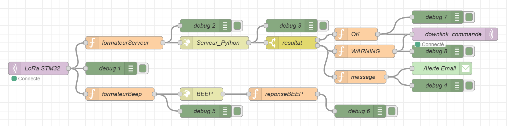
TTN → MQTT in Node (Node-RED) → Data Formatter → HTTP Request Node → BEEPDownlink Process :
**Closed-loop control: Cloud → STM32 frequency adjustment**
STM32 opens two short “receive windows” (1–2 s each) immediately after every uplink transmission. This lets us send configuration commands back to STM32.
1. Anomaly Detection (Python Server)
- Receives data from TTN via Node-RED.
- Validates sensor values against predefined thresholds and returns a JSON response:
{"status": "OK/WARNING", "details": "Anomaly description"}2. Downlink Command Logic
WARNING State :
Node-RED triggers:
- Downlink Command: Send
0x01(base64:AQ==) to STM32 → Increases transmission frequency to 2 mins. - Email Alert: an email node alerts the client of the detected issue.
- Note: To avoid spamming, each distinct problem triggers only one email; repeated warnings for the same condition do not generate additional messages.
OK State :
- Send
0x00(base64:AA==) → Reverts to the normal 10-min transmission cycle.
For more informations :
- LoRaWAN Protocol: why this choice?
Regarding the specifications of our system, we need to transmit our data over a pretty large distance while consuming the least power possible. Our data were scaled down to numerical-type values in order to keep them the simplest and lightest possible (< 30 bytes). Since a LoRa gateway is installed near the beehive and our data are pre-processed using a stack on The Things Network, we chose to use the LoRaWAN protocol.
- Integration on STM32WL
As explained in section Ⅳ, a LoRa module is integrated to the board. And with the library STM32duino LoRa WAN defined with examples in Arduino IDE, it's pretty simple to send data. Its power is linked to the board but it is possible to power it down individually when unused; which was hard to implement so we didn't do it.
- Sent data format
All data transmitted from the board was of numerical-type (float/int), as done in the code below:
// Include library
#include <STM32LoRaWAN.h>
//...
// Define modem LoRa instance
LoRaModem modem;
//...
// Setup function
void setup(){
    // other initializations
    int connected = modem.joinOTAA(appEui, appKey, devKey); //your credentials
    if (!connected) {
        Serial.println("Connection OTAA failed, please retry");
        while (1) {}
    }
    Serial.println("Connected to LoRaWAN !");
    //...
}
// Loop function
void loop(){
    // acquire data from sensors
    sendLoRaData(...);
    // Go into sleep mode
}

void sendLoRaData(float t22_1, float h22_1, float t22_2, float h22_2, float tempC1,
float tempC2, float light, float weight) {
    uint8_t txData[20];
    int16_t t22_1_int = t22_1 * 10;
    int16_t h22_1_int = h22_1 * 10;
    int16_t t22_2_int = t22_2 * 10;
    int16_t h22_2_int = h22_2 * 10;
    int32_t tempC1_int = tempC1 * 100; // accuracy to the hundredth
    int32_t tempC2_int = tempC2 * 100; // accuracy to the hundredth
    int16_t light_int = light;
    int32_t weight_int = weight * 100; // accuracy to the hundredth
    // Packing data
    txData[0] = t22_1_int >> 8;
    txData[1] = t22_1_int & 0xFF;
    txData[2] = h22_1_int >> 8;
    txData[3] = h22_1_int & 0xFF;
    txData[4] = t22_2_int >> 8;
    txData[5] = t22_2_int & 0xFF;
    txData[6] = h22_2_int >> 8;
    txData[7] = h22_2_int & 0xFF;
    txData[8] = tempC1_int >> 24;
    txData[9] = tempC1_int >> 16;
    txData[10] = tempC1_int >> 8;
    txData[11] = tempC1_int & 0xFF;
    txData[12] = tempC2_int >> 24;
    txData[13] = tempC2_int >> 16;
    txData[14] = tempC2_int >> 8;
    txData[15] = tempC2_int & 0xFF;
    txData[16] = light_int >> 8;
    txData[17] = light_int & 0xFF;
    txData[18] = weight_int >> 8;
    txData[19] = weight_int & 0xFF;
    modem.beginPacket();
    modem.write(txData, sizeof(txData));
    int err = modem.endPacket(true);
    if (err > 0) {
        Serial.println("✅ Data sent successfully!");
    } else {
        Serial.println("❌ Failed to send data.");
    }
}
❗`t22_1` and `h22_1` resp. refer to the central temperature and humidity inside the hive, acquired by the inner DHT22; `t22_2` and `h22_2` resp. refer to the temperature and humidity outside the hive, acquired by the outer DHT22; `tempC1` and `tempC2` resp. refer to the temperatures on the inner sides of the hive, acquired by the two DS18B20; `light` refers to the outside light intensity, acquired by the TSL2861; `weight` refers to the weight of the hive, acquired by the HX711 and the scale.
Ⅶ) Arduino ShieldIn the end, we need what is called a shield on our electronic board. A shield serves the same purpose as a PCB (Printed Circuit Board) and helps connect the sensors to the board. To create this shield, we will use the KiCad 9.0 software, as it already provides templates.
Our electronic board is the STM32WL55JC1, which has the same pinout as the Arduino Uno board. Therefore, we can use the Arduino Uno Shield template to create our own.
As you can see, there are 8 connectors which are used by :
- DHT22 : humidity and temperature → 2 connectors (grove)
- DS18B20 : temperature → 2 connectors (grove)
- TSL2561 : luminosity → 1 connector (grove)
- HX711 : weight → 1 connector (grove)
- Alim1 : alimentation → 1 connector (grove)
- Pololu-3v3 : 3v3 regulator → 1 connector (normal)
Grove : Through hole straight pin header, 1x04, 2.00mm pitch, single row.
Normal : Through hole straight pin header, 1x04, 2.54mm pitch, single row.
The 2 resistors are used for the ADC pin to monitor the battery status.
Ⅷ) Power management and robustnessOur system uses a 2200mAh LiPo battery to ensure long-term operation. A solar panel is also included to recharge the battery during the day. However, in case of cloudy weather or no sunlight for up to three days, the large capacity of the battery helps maintain continuous operation without interruption.
To reduce energy use, we follow a low-power strategy. The STM32 microcontroller enters deep sleep mode for long periods (up to 10 minutes) using the STM32duino Low Power library. Unused pins are set to analog mode to reduce power loss, and a physical switch can cut off all power to the system when needed.
Another important component is a 3.3V voltage regulator (Pololu). It is used because some sensors still consume current even during deep sleep, which can waste energy. To avoid this, the STM32 board controls the regulator with a GPIO pin. Before entering sleep mode, the board disables the regulator by turning off the GPIO pin, stopping the power supply to the sensors and saving energy.
For physical protection, the enclosure is made to resist rain, moisture, and shocks :
- Rubber seals are used to prevent water from entering the box.
- Cable glands (used to hold and seal cables at the entry point) are also installed to stop water from leaking in through the cables.
- We extended the sensor cables and added protective tubing to shield them from damage caused by friction or outdoor conditions.
- To further protect the electronics, a small silica gel packet (moisture absorber with beads inside) is placed inside the box to limit humidity buildup.
- As for the light sensor, it is placed in a separate enclosure to allow it to detect sunlight properly without being blocked or affected by the hive environment.
Throughout the development of the system, several technical challenges emerged, each requiring specific solutions or workarounds to ensure proper functionality and reliability in real-world conditions.
Integrating the STM32 microcontroller (alternative to Arduino-based boards) brought additional complexity. While the STM32 offers better performance and lower power consumption, its software environment was less straightforward.
One of the most persistent challenges we encountered was implementing a method to monitor the battery level. Our initial plan was to use a simple voltage divider connected to an analog input pin, in order to read the LiPo battery voltage. However, despite several attempts to connect the divider across different branches, each time adjusting the resistor values and trying various positions between VBat, GND, and analog inputs, we were unable to get stable or reliable readings. Either the readings remained stuck, or the values returned were completely inconsistent with the actual voltage. Faced with these difficulties, we considered using a dedicated voltage sensor module as an alternative. This solution would have offered better reliability and easier calibration, but due to its relatively high cost and long delivery time, we were unable to include it in the project within the available timeline. Nonetheless, this remains the most viable option for future iterations.
We also faced significant issues when trying to implement low-power modes such as Stop Mode and Standby to reduce energy consumption. Although we initially planned to use these modes, which offer the best power-saving performance, we were ultimately unable to integrate them successfully. Despite several attempts, the microcontroller either failed to enter these modes or did not wake up correctly, especially after we added multiple sensors into the code. These low-level modes require precise handling of wake-up sources and sensor reinitialization, which proved too unstable with our current setup. As a result, we had to fall back on a more basic Deep Sleep approach, which, while less efficient, provided more predictable and stable behavior. This standard Deep Sleep allowed us to reduce power consumption to some extent without compromising the overall acquisition process. In future versions, a full implementation of Stop or Standby modes would require deeper integration with sensor drivers and a more robust power management strategy, which we were unable to complete within the time constraints of this project.
Ⅹ) Conclusion and outlookThrough this project, we have explored the intersection between environmental responsibility and technological innovation. The alarming decline in bee populations calls for urgent and concrete solutions, and connected beekeeping represents a promising step in that direction. Although our implementation faced challenges, such as power optimization difficulties and hardware integration limits, we succeeded in building a functional and modular prototype capable of monitoring hive conditions in real-time.
Beyond its immediate technical scope, this project offered us the opportunity to reflect on how embedded systems and IoT can serve ecological causes. The development process also emphasized the importance of simplicity, reliability, and adaptability when designing tools meant to operate in sensitive natural environments.
Looking ahead, there is significant room for improvement: battery level monitoring, more advanced energy-saving strategies, and robust long-term data analytics are all features that could elevate the system further. With continued iteration and collaboration, this kind of smart monitoring could empower beekeepers globally to better protect their colonies and by extension, biodiversity itself.
In the end, our work was not just an academic exercise, but a meaningful contribution to an ongoing global effort. If our system can support even a small part of the fight against pollinator decline, then the project has fulfilled its most important mission.


_Ujn5WoVOOu.png?auto=compress%2Cformat&w=40&h=40&fit=fillmax&bg=fff&dpr=2)


Comments