

Hardware components | ||||||
 |
| × | 5 | |||
 |
| × | 3 | |||
 |
| × | 3 | |||
 |
| × | 1 | |||
 |
| × | 3 | |||
 |
| × | 5 | |||
| × | 1 | ||||
Software apps and online services | ||||||
| ||||||
| ||||||
RT-SPARK (SPARK-1) RT-THREAD DEVELOPMENT BOARD
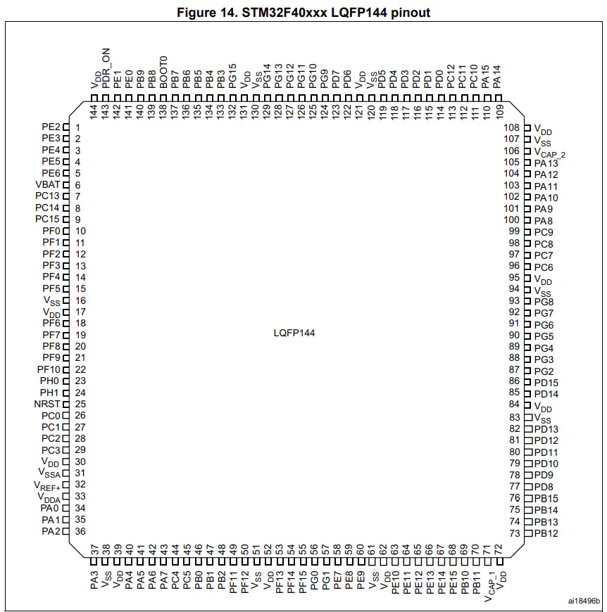
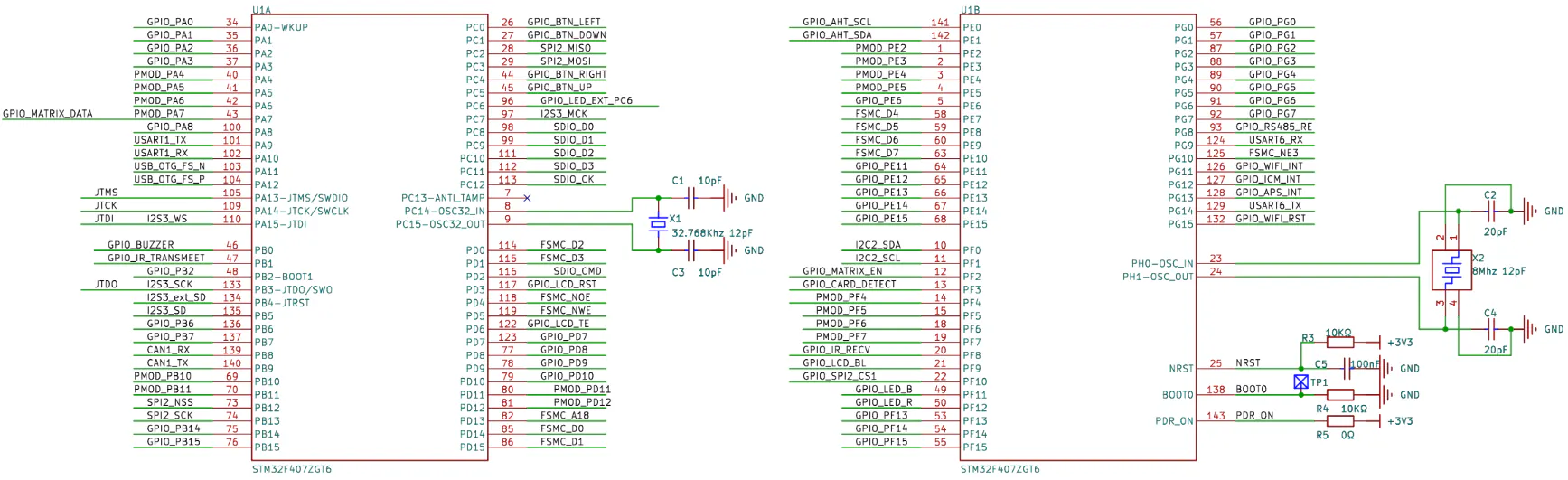
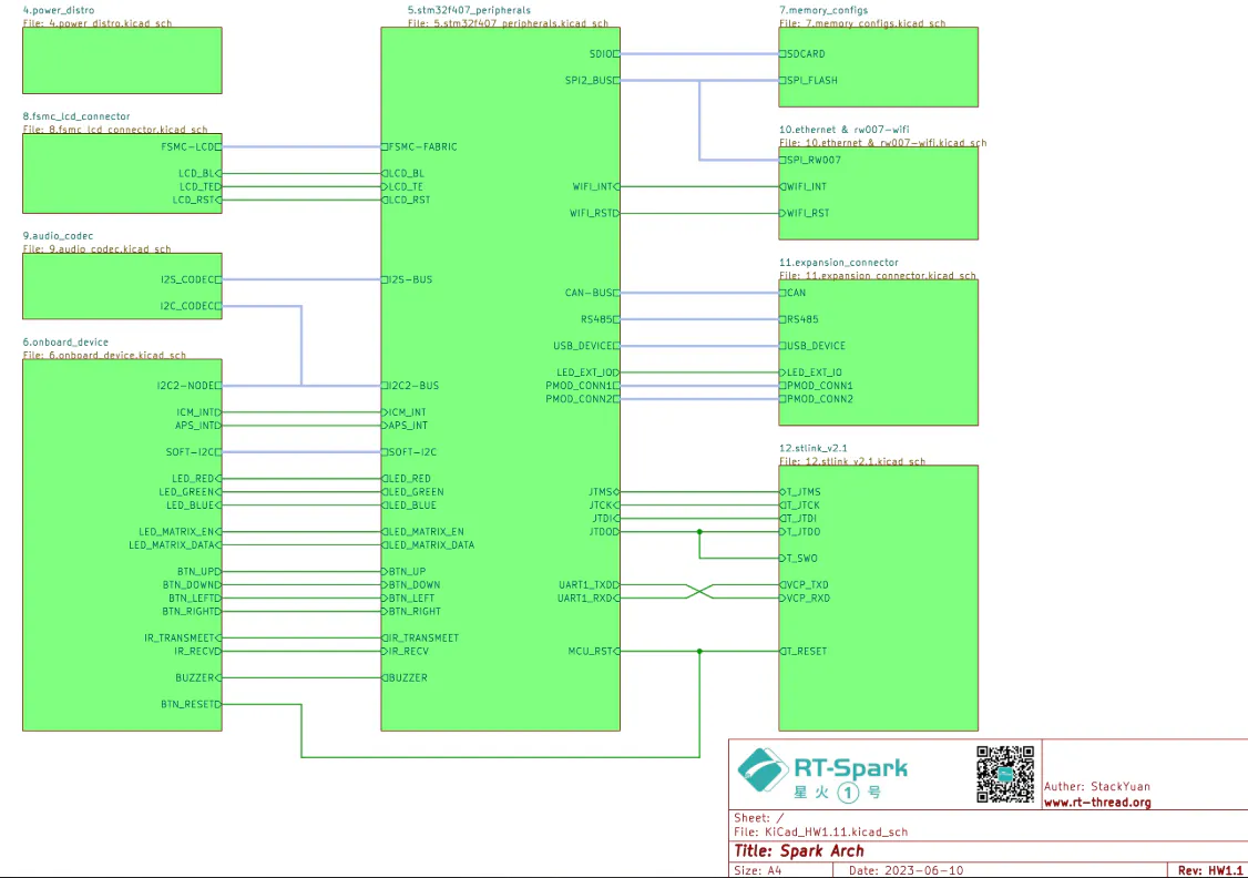
The RT-Spark, also known as "Spark-1", is a Development board made by RT-Thread, which uses the "STM32F407ZGT6" Microcontroller(MCU). Not only it is embedded with that MCU chip, it also features a few other components, such as Wi-Fi, Buzzer, SD-Card, LED Matrix, and most importantly, the LCD.
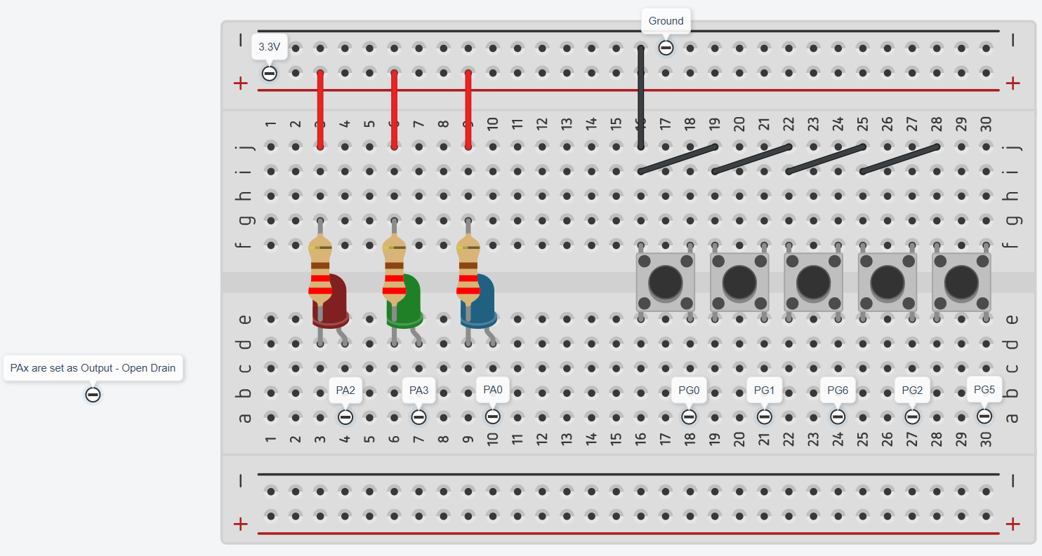
For this scenario, the main highlight would be the built-in LCD, which contains 240x240 resolution/pixels that utilizes the Flexible static Memory Controller(FSMC) peripheral communication, then some other implementations, such as 5 momentary switches, and 3 different color LEDs or 1 RGB LED.
BACKLIGHT BUILT-IN LCD
Before proceeding to the upcoming steps, it is recommended to ensure that the built-in LCD is still working or you'll end up sitting for hours and achieve absolutely nothing.
First, create a new STM32 Project, choose the STM32F407ZGT6 MCU, and let the default settings work by itself.
Then, locate the backlight pin to set as an output, generate the CubeMX code, and turn on the pin.
OUTPUT:
The LCD backlight should light up. Meaning, the backlight is fine, but not yet sure for the LCD.
CONFIGURING THE PERIPHERAL COMMUNICATION FOR THE BUILT-IN LCD
The built-in LCD uses the ST7789 v3 Driver Chip, and the communication interface is 8080 parallel port, thus the MCU uses the FSMC peripheral communication. To start, we must setup the FSMC to allow us to communicate with the built-in LCD.
First, locate the LCD's reset pin, set it as output, and follow the same steps as we did from the LCD backlight pin.
Second, configure the FSMC to work with the LCD interface. After that, update/generate the CubeMX Code.
TWO WAYS TO USE THE LCD
There are two ways to approach when it comes to using the built-in LCD; first, the easy method, which is what this guide is leading to, or the manual approach, from manually turning on the backlight, resetting the configuration, initializing the display, and write data to the screen pixel by pixel.
The code written from the previous instructions was part of the manual configuration of the LCD, specifically for the backlight.
DOWNLOADING BUILT-IN LCD’S HEADER & SOURCE FILES
To avoid doing everything manually, it's essential to download the developers' Software Development Kit(SDK) from the GitHub repository, but that version requires you to have the Real-Time Operating System(RTOS) while this guide uses bare-metal. Therefore, it is recommended to use the Project-Used Libraries if you want a bare-metal approach:
Official - https://github.com/RT-Thread-Studio/sdk-bsp-stm32f407-spark
Project-Used Lib - https://sendgb.com/M8kq5c23FwC
After downloading both the folders “Header, Source Files”, put them into their respective folders from the Project.
Header Files (.h) = ProjectName/Core/Inc
Source Files (.c) = ProjectName/Core/Src
Lastly, declare the inclusion of the "drv_lcd.h" Header File, and the LCD's functions will now be accessible.
Functions and Definitions
Commonly used functions:
- drv_lcd_hw_init() -
Turns on backlight, resets and initializes LCD - lcd_clear() -
Clears the screen and changes the background color - lcd_show_string() -
Allows you to Write character/s or strings - lcd_draw_point() -
draws a dot/pixel to the screen - lcd_draw_circle() -
draws a circle to the screen - lcd_draw_line() -
draws a line to the screen - lcd_draw_rectangle() -
draws a rectangle to the screen
List of functions that are listed from the “drv_lcd.h, drv_lcd.c”:
OUTPUT (INCLUDING 5 SWITCHES & 3 LEDS):
If you wish to follow this setup, simply copy the codes, including the pins used below (unless you know what you're doing).


Comments