

Hardware components | ||||||
 |
| × | 1 | |||
 |
| × | 1 | |||
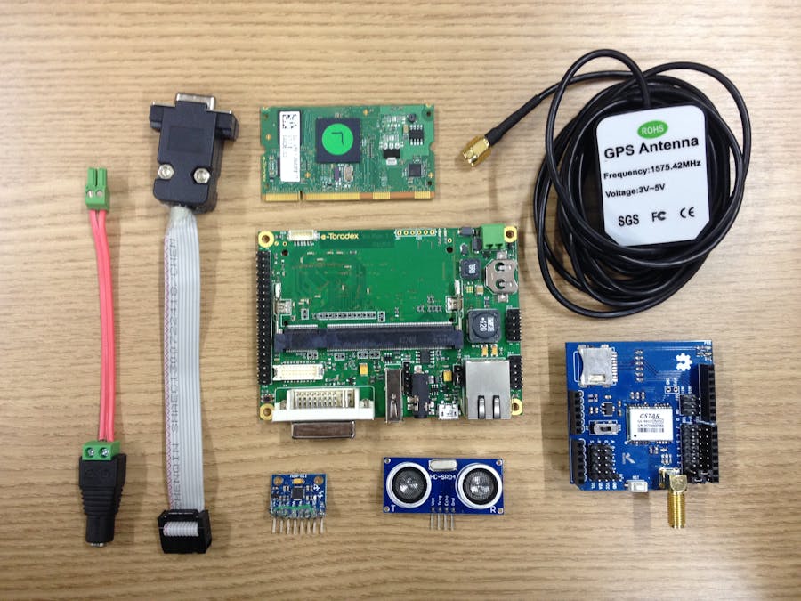
This project implements an IoT solution whose goal is to interface a Toradex SBC solution - Colibri VF61 CoM (NXP Vybrid SoC) + Iris Carrier Board - to 3 sensors/modules and send the gathered data to the Microsoft Azure IoT Hub using Node.js. The chosen modules are the HC-SR04 (ultrasonic distance measure), MPU-6050 (accelerometer, gyro and temperature) and a generic GPS module.
Step 1: wiring the modules to the SBCThe first step is to connect the modules to the Iris carrier board pin-header (X16), having a breadboard as the wiring interface.
- To supply +5V to the breadboard, connect the Iris pin 12 (+5V/VCC) to the positive bus strip and the Iris pin 7* (GND) to the negative bus strip.
- For the MPU 6050 module, connect the VCC and GND pins to the respective breadboard buses. Connect the SDA pin to the Iris pin 5 (I²C-SDA) and the SCL pin to the Iris pin 6 (I²C-SCL); also connect the AD0 pin to the Iris pin 33 (+3.3V).
- For the HC-SR04 module, connect the VCC and GND pins to the respective breadboard buses. Connect the TRIG pin to the Iris pin 17 (GPIO) and the ECHO pin to the Iris pin 18 (GPIO).
- For the GPS module, connect the VCC and GND pins to the respective breadboard buses (if your GPS module works with +3.3V, use the Iris pin 33 instead of the breadboard positive +5V bus strip; also some GPS modules have a switch to select between +3.3V or +5V). Connect the Tx pin to the Iris pin 31 (UART-B Rx) and the Rx pin to the Iris pin 32 (UART-B Tx).
In order to configure the modules interfaces, the steps described below must be followed.
Flashing Linux to the Colibri VF61
Once the default images provided by Toradex do not come with the GPSD service pre-installed, we will create our own image with the OpenEmbedded framework. If you want to use a default image and install the GPSD from userspace, there are some useful information here.
Install OpenEmbedded by following this OpenEmbedded guide.
Inside the OpenEmbedded build directory, add the following line to the end of the conf/local.conf file:
IMAGE_INSTALL_append = "gpsd"
Then build the image for our application with the bitbake command. Notice it may take hours to finish:
bitbake console-trdx-image
After building is done, refer to the previously cited OpenEmbedded guide to find the image path in your host machine and flash it to the Colibri VF61.
Connecting to the embedded system
Before plugging your module to a power supply, plug the USB connector of the serial to USB adapter to your development machine. Also, use the DB9 to pin-header cable to connect the Iris UART (pin-header X13) to the adapter. Be careful not to invert the pin-header connector. Useful information can be found in the Iris technical datasheet - section 3.9.1.
Then, power-up the Iris and connect to it from the development machine terminal by using a terminal emulator such as picocom, with a baud-rate of 115200:
sudo picocom -b 115200 /dev/ttyUSBx #the "x" in USBx is a number that may vary
Configuring the sensors/modules
- MPU-6050 (accelerometer/gyro/temperature)
The MPU-6050 sensor already has a module in the Kernel version 4.4 revision by Toradex, but the image we built previously comes with the 4.1, so it is needed to compile the newer Kernel version with the MPU-6050 driver enabled and deploy it to the board. Information regarding how to do it can be found in the build Kernel from source guide. Also, the Kernel source-code can be retrieved from the Toradex git repository.
Also, the device tree fragment below, adapted from here, must be added so the I²C controller knows about the sensor module and its address. Notice it must be added to the &i2c0 node of the device tree, which already has a touch and rtc descriptions:
mpu6050@69 {
   compatible = "invensense,mpu6050";
   reg = ;
   interrupt-parent = ; /*not so important since interrupt isn' being used*/
   interrupts = ;
};
Below there are some instructions that may help through the process, though it is still needed to follow the build Kernel from source guide presented above.
# Download Kernel source code
git clone -b toradex_vf_4.4-next git://git.toradex.com/linux-toradex.git
cd linux-toradex
# Configure Kernel
colibri_vf_defconfig
make nconfig
# Edit device tree to add the MPU-6050 fragment
vim $(find . -name "vf-colibri-eval-v3.dtsi")
# Compile Kernel and device tree
make -j3 zImage | tee build.log
make vf610-colibri-eval-v3.dtb
- HC-SR04 (ultrasonic distance meter)
This sensor has a Kernel module already compiled for this Kernel version and hardware in this Github repository. The source-code is also present, if you want to adapt it to your needs. All you need to do is to copy the hcsr04.ko file into your home folder:
cd ~
git clone https://github.com/leograba/hc-sr04.git
cd hc-sr04
cp hcsr04.ko ~
# optionally you can delete the repository
cd ~
rm -r hc-sr04
- GPS module
Since we will communicate with the GPS module by the GPSD service, which is already installed, the only steps required are to configure the service whenever the embedded system is powered-on or reset. This will be accomplished below in the init script subsection:
- Init script
To autorun the application at startup, we will create and enable a service that calls our init script. The following content must be added to the file /etc/systemd/system/car.service that must be created:
[Unit]
Description=Azure Example
After=multi-user.target
[Service]
Type=simple
ExecStart=/home/root/azure-iot/init.sh
[Install]
WantedBy=multi-user.target
Then to enable the service to start at boot time:
systemctl --system daemon-reload
systemctl enable car.service
Now we are able to create the init script file /home/root/azure-iot/init.sh, which starts the GPSD service, load the HC-SR04 and MPU-6050 kernel modules and starts the node application to be developed in the next section:
#!/bin/sh
sleep 2
stty speed 9600
gpsd -n /dev/ttyLP2
insmod /home/root/azure-iot/hcsr04.ko # ultrassonic module
modprobe inv-mpu6050 # Gyro/accelerometer module
while : ; do
       node /home/root/azure-iot/send_data_from_sensors.js
	sleep 2
done
Node.js and packages installation
In order to run a Node.js application in the embedded system, Node.js and the required modules for this project must be installed. First install Node.js and the package manager NPM:
opkg install nodejs nodejs-npm
Then create the file /home/root/azure-iot/package.json:
{
 "name": "trdx_iot_car",
 "version": "0.0.1",
 "private": true,
 "description": "Sample to send data to the IoT Hub using Node.js",
 "author": "Leonardo Graboski Veiga",
 "license": "MIT",
 "dependencies": {
   "azure-iot-device": "1.0.1",
   "azure-iot-device-http": "1.0.1",
   "bancroft": "0.0.12"
 },
 "devDependencies": {
   "jshint": "^2.8.0"
 }
}
And finally to install the packages, run:
cd ~/azure-iot
npm install
Summary
Briefly, the code steps to be developed are the following:
- 1) Load the Azure-IoT, Bancroft and filesystem libraries
- 2) Configure the Azure IoT Hub related part
- 3) Read sensors constant values synchronously, thus preventing wrong environment reading due to the Javascript asynchronous behavior
- 4) Configure what happens on GPS events that we are interested in
- 5) Write a function to read a single sensor and then another function that reads all sensors
- 6) Write a function that encode, encapsulate and send data to the IoT Hub
- 7) Call both getAllSensors and sendToIotHub in separate loops, which makes the code more flexible for future improvments/possibilities
Code development
First create the file /home/root/azure-iot/send_data_from_sensors.js, then open it in your favorite text editor. Notice you can just copy the final result from the project GitHub in order to avoid typing or copy/pasting the following code portions.
1) Below the required modules for the project are added. It is pretty straightforward:
'use strict';
// Required modules and functions
var Protocol = require('azure-iot-device-http').Http;// The transport protocol
var Client = require('azure-iot-device').Client;
var Message = require('azure-iot-device').Message;
var Bancroft = require('.
ode_modules/bancroft/bancroft.js');
var bancroft = new Bancroft();
var fs = require('fs');
2) Now the client to send data to the IoT Hub will be configured. Notice the variable connectionString must hold the connection string related to your IoT Hub, which will be addressed later in the step 4. Just leave as it is for now.
// Create client to connect to the IoT Hub using the device connection string and the HTTP protocol
var connectionString = "HostName=yourHostName.azure-devices.net;DeviceId=yourDevice;SharedAccessKey=yourSharedAccessKey";
var client = Client.fromConnectionString(connectionString, Protocol);
3) Read the sensor constants (synchronous file read) and declare/set variables related to loop handling and data readings:
//Read some offset and scale constants from the MPU-6050 and convert to number
var temp_offset = +fs.readFileSync('/sys/bus/iio/devices/iio:device2/in_temp_offset');
var temp_scale = +fs.readFileSync('/sys/bus/iio/devices/iio:device2/in_temp_scale');
var accel_scale = +fs.readFileSync('/sys/bus/iio/devices/iio:device2/in_accel_scale');
var anglvel_scale = +fs.readFileSync('/sys/bus/iio/devices/iio:device2/in_anglvel_scale');
// Data to be sent
var timenow, temperature, Distance, gps_coordinates, Acceleration = {}, Gyroscope = {};
// Loop handler
var sendInterval = {timerGet:1000, timerSend:1000};
4) Configure the GPS events. The location event is triggered whenever new coordinates are read and it updates the GPS information variable. The disconnect event happens if the module is for some reason disconnected and it attempts to reconnect.
/ gps events
bancroft.on('location', function (location) {//updates the gps coordinates variable
	location.geometries = "point";
	gps_coordinates = location;
	console.log('got new location', gps_coordinates);
});
bancroft.on('disconnect', function (err) {//if gps is disconnected
	bancroft = new Bancroft();//tries to reconnect once
	console.log('trying to reconnect gps...');
});
7) Yes it is out of the list order, sorry! But I think it is best to separate the code functions from the code logic, in an attempt to keep everything organized. This part is very simple, it just set functions to be called periodically:
// Loops that call the functions to read sensors and send to the cloud
sendInterval.handlerGet = setInterval(getAllSensors, sendInterval.timerGet);
sendInterval.handlerSend = setInterval(sendToIotHub, sendInterval.timerSend);
5) The function that reads a single sensor is basically a read file operation that has a predefined error handling - it only prints the error to the console and the code keep running. I think it is a good approach because if you have the application running in the field and a sensor fails, it is better to handle it in the cloud than to stop sending data.
The function that reads all sensors gets the embedded system timestamp, reads all sensors files and performs some elementary math operations.
//Function that reads data from sensor
function readSensor(path, callback) {
	fs.readFile(path, function (err, data) {
		if(err){//if data could not be read
			console.log("Error reading sensor: " + err);
			callback(err, null);//pass the error to the callback
			return;
		}
		callback(null, data);//callback without error
	});
}
//Function that reads all sensors data
function getAllSensors() {
	var d = new Date();
	timenow = d.getTime();// get board time (in Epoch time)
	readSensor('/sys/class/hcsr04/value', function(err,data){
		if(data != -1){//check if sensor reading was successful
			Distance = data*340/2000000;//Get distance reading
		}
	});
	readSensor('/sys/bus/iio/devices/iio:device2/in_temp_raw', function(err,data){
		temperature = (+data+temp_offset)*temp_scale;//Get temperature reading
	});
	readSensor('/sys/bus/iio/devices/iio:device2/in_accel_x_raw', function(err,data){
		Acceleration.accel_x = data*accel_scale;//Get x axis acceleration
	});
	readSensor('/sys/bus/iio/devices/iio:device2/in_accel_y_raw', function(err,data){
		Acceleration.accel_y = data*accel_scale;//Get y axis acceleration
	});
	readSensor('/sys/bus/iio/devices/iio:device2/in_accel_z_raw', function(err,data){
		Acceleration.accel_z = data*accel_scale;//Get z axis acceleration
	});
	readSensor('/sys/bus/iio/devices/iio:device2/in_anglvel_x_raw', function(err,data){
		Gyroscope.gyro_y = data*anglvel_scale;//Get x axis gyro
	});
	readSensor('/sys/bus/iio/devices/iio:device2/in_anglvel_y_raw', function(err,data){
		Gyroscope.gyro_z = data*anglvel_scale;//Get y axis gyro
	});
	readSensor('/sys/bus/iio/devices/iio:device2/in_anglvel_z_raw', function(err,data){
		Gyroscope.gyro_z = data*anglvel_scale;//Get z axis gyro
	});
}
6) Finally, a function to send data to the cloud is written - it encodes the data in the JSON format, encapsulates it using a function provided by the azure module, log a message and send the data. A helper function is also written to print the data sending results.
function sendToIotHub() {
	// Add the data to a JSON encoded string
	var data = JSON.stringify({
		ObjectName: 'toradex2',
		ObjectType: 'SensorTagEvent',
		temp: temperature,
		acceleration: Acceleration,
		gyroscope: Gyroscope,
		gps: gps_coordinates,
		distance: Distance,
		boardTime: timenow
	});
	var message = new Message(data);// Encapsulate the message to be sent
	message.properties.add('myproperty', 'myvalue');
	console.log('sending message to the IoT Hub: ');// Feedback message to the console
	console.log(data);
	client.sendEvent(message, printResultFor('send'));// Send message to the IoT Hub
}
//Helper function to print results in the console
function printResultFor(op) {
 return function printResult(err, body, res) {
   if (err) console.log(op + ' error: ' + err.toString());
   if (res){
     console.log(op + ' response: ' + res);
     console.log(body);
   }
 };
}
Azure setup
Setup an IoT Hub as described here. As a final step, get the IoT Hub connection string, which is found in the Azure portal as described in this paragraph's link to the setup and also on the figure below:
In your development machine, add a device to your IoT Hub as described here and summarized below:
#install the required IoT Hub management tool
npm install -g iothub-explorer
# Use the recently acquired connection string and choose a device name
iothub-explorer  create  --connection-string
Copy the device connection string to the variable connectionString in your Node.js application.
Ready to go
On the development machine, run the iothub-explorer tool, previously installed, to see the data being received:
iothub-explorer monitor-events
In the embedded system, run the Node.js application as stated below or alternatively, just reboot (because the previously created service starts the application at boot time):
cd ~/azure-iot
node send_data_from_sensors.js
You must soon see data on the development machine as illustrated in the figure below, which confirms everything is working correctly:


Comments