

Hardware components | ||||||
 |
| × | 1 | |||
| × | 1 | ||||
| × | 1 | ||||
 |
| × | 1 | |||
| × | 3 | ||||
 |
| × | 1 | |||
 |
| × | 1 | |||
 |
| × | 4 | |||
| × | 1 | ||||
 |
| × | 1 | |||
 |
| × | 3 | |||
 |
| × | 1 | |||
 |
| × | 1 | |||
Software apps and online services | ||||||
 |
| |||||
Hand tools and fabrication machines | ||||||
 |
| |||||
| ||||||
I upgraded this project by designing a PCB with more features, you can inspect the enhanced version from here :)
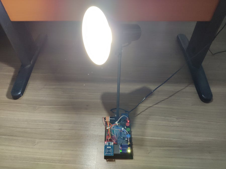
DescriptionI have had an old and, not surprisingly, a dilapidated desk lamp for a long time and I thought it would be more effective and useful by getting upgraded with an MFRC522 RFID reader. But I, also, wanted to personalize it by using a specialized color pattern to turn the lamp off, hence the use of potentiometers and RGB LED.
To support my projects and articles, you can visit my website here :)
First of all, download MFRC522 library from this link.
1 ) Solder male headers to MFRC522 RFID reader with a soldering iron carefully.
2 ) If you do not save or register an UID to EEPROM, use the function - registerCardUID() - below by uncommenting it from setup().
3 ) After saving get the UID from EEPROM by using this function.
4 ) And the final step, just compare the saved UID and the UID read by MFRC522 to turn the lamp and control LED on.
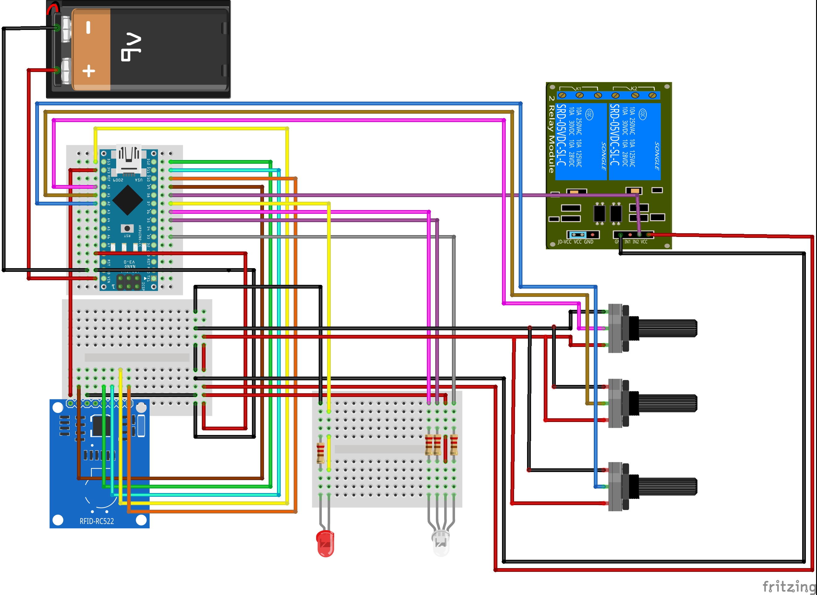
Components connections are well-explained at the source code down below, make sure defining RST and SS pins properly.
Connect all components to Arduino Nano.
Rearrange your lamp parts to make components fit in it perfectly.
And then, sturdier all components via a hot glue gun.
ON :
When MFRC522 RFID reader reads the same UID saved by EEPROM accurately.
- Turn control LED and the lamp turn on.
OFF :
When all potentiometer values are turned into zero.
Red Potentiometer Value = 0;
Green Potentiometer Value = 0;
Blue Potentiometer Value = 0;
- Turn control LED, RGB LED and the lamp off.


_3u05Tpwasz.png?auto=compress%2Cformat&w=40&h=40&fit=fillmax&bg=fff&dpr=2)
Comments