

Hardware components | ||||||
 |
| × | 1 | |||
| × | 1 | ||||
 |
| × | 1 | |||
 |
| × | 4 | |||
| × | 1 | ||||
Software apps and online services | ||||||
 |
| |||||
| ||||||
 |
| |||||
| ||||||
It is the second demonstration project about TheAmplituhedron IoT Services programmed by myself in HTML and PHP, as anew feature for my website subscribers if you want, you can view the first project on here. In this project, I want to use TheAmplituhedron IoT Services as an online RGB color detector hence the use of the TCS3200 RGB Color Sensor. So, by using IoT Services, you can view colors in RGB format between 255 and 0 on your dashboard. I thought that sending colors in RGB format over the Internet from NodeMCU to the database that of my website through your account on TheAmplituhedron would exemplify the variety of the possibilities in the Internet of Things. In every 2 seconds, you can monitor colors detected by the TCS3200 Color Sensor through TheAmplituhedron database via NodeMCU. Nonetheless, you can use any other device that is capable of making HTTP Get Requests instead of NodeMCU. Most importantly, you can use TheAmplituhedron IoT Services by signing in with your Gmail or Twitter account in the full and free version. The bottom line is that it is an online color detector sending data packets to the database dedicated to your account hedron in RGB format, allowing you to monitor the recent data packets as colors.
Aside from the cloud system of TheAmplituhedron used in other projects of mine, TheAmplituhedron IoT Services is for displaying and saving data packets received from NodeMCU etc. in HTTP Get Request Method only. Like the cloud system of TheAmplituhedron that can receive and transmit data packets through web server in either HTTP Get Request or HTTP Post Request, specialized for Arduino Ethernet Shield and Raspberry Pi, TheAmplituhedron IoT Services is programmed by myself in PHP, jQuery and AJAX as an available system for only my website subscribers. But, as opposed to the cloud system of TheAmplituhedron, it can only receive data packets in HTTP Get Request Method, and display recent data packets only; TheAmplituhedron IoT Services is dedicated to showing the recent data gathered by NodeMCU etc. via sensor readings properly through TheAmplituhedron database and server. To use this feature, please follow the steps down below and subscribe to my website if you have not yet.
How can I subscribe to TheAmplituhedron?It is very simple to subscribe to benefit all available system provided by me; you just have to sign up to TheAmplituhedron.com, which is programmed by myself.
As showed by the figure down below, you have three options to sign up - Sign In with Google Plus, Continue with Twitter and Sign Up(Create an account).
1) Sign In with Google Plus
Just click Sign In with Google Plus and accept permissions. After that, you are ready to use IoT Services freely.
2) Continue with Twitter
Just click Continue with Twitter and authorize TheAmplituhedron. After that, you are ready to use IoT Services freely.
3) Sign Up
Or, if you do not want to use a third party account for verification, you can create your own account on TheAmplituhedron, as depicted down below.
After signing up process, your hedron - the unique 20-digit ID that used as an identifier in your connection path URL - generated by the server; you can display it under personal information section.
Personal Information -> Hedron -> Display
After subscribing, you have to create your unique connection path URL under IoT Services on your dashboard. Just click Create+ to auto-generate your connection path URL; after clicking, a pop-up bar will re-direct you to your connection path URL, containing your username and hedron.
Do not forget that you can create one connection page named with your username, and save in a constricted database - up to 6 entry.
Your secure connection path should be like this;
/dashboard/IoTServices/USERNAME-HEDRON
Now. you can send data packets - up to 6 entry - by using HTTP Get Request Method like here.
Syntax :
?dataNameFirst=
&dataNameSecond=
&dataNameThird=
&data1=
&data2=
&data3=
NodeMCU is an open source IoT platform, and also the name of an ESP8266 integrated development board. I used a ESP-12E V2.0 2.4Ghz in this demonstration project.
First of all, download its default board along with libraries from GitHub on here.
Add, the included libraries in the source code from example files - the rest of it is well-explained at the source code down below.
To make an HTTP Get or Post Request is simple and easy with HTTPClient Library, but if you make this request to a website protected with SSL Certificate like my website(TheAmplituhedron.com), you may need to learn how to manage to glean a website SSL FingerPrint or ThumbPrint from here.
http.begin(connectionPath, "SSL FingerPrint or ThumbPrint");
How to detect colors in RGB format by using a TCS3200I wanted to transfer colors as data packets over the Internet in this project but to achieve this, I needed to detect colors and turn them into integer values hence the use of the TCS3200 Color Sensor. It is a programmable color light - to -frequency converter that combine configurable silicon photodiodes and a current-to-frequency converter on a single monolithic CMOS integrated circuit. Basically, it includes red, blue and green square-wave frequency detector at its core. Depending to the surrounding brightness and its scaling value, TCS3200 sensors turn the detected frequency as integers. Most importantly, it allows you to get data from each photodiode group one by one. That is actually the trick to elicit color codes in RGB format. The reason is as follows. When you map the detected frequencies from 255 to 0, you get the approximate RGB codes in order, like (255, 255, 255).
As depicted below. you can choose the scaling value and the active photodiode detector. For instance, you can detect green in 20% scaling under a bright light source.
So you can switch between photodiodes and scaling values to detect colors in RGB format accurately as showed at the source code.
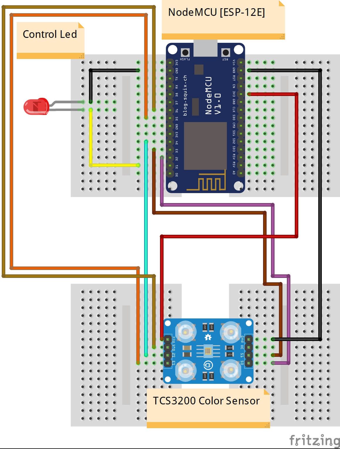
Connect the TCS3200 to the NodeMCU [ESP 12-E] as showed at the source code introduction in which all connections details are well-explained.
Do not forget to attach the control led informing you whether the WiFi connection is ready to transfer data packets to the assigned database or not.
Now, after all these steps, there is one thing to do to use TheAmplituhedron IoT Services in a proper way. Before uploading the source code, enter your WiFi settings, account information and SSL FingerPrint.
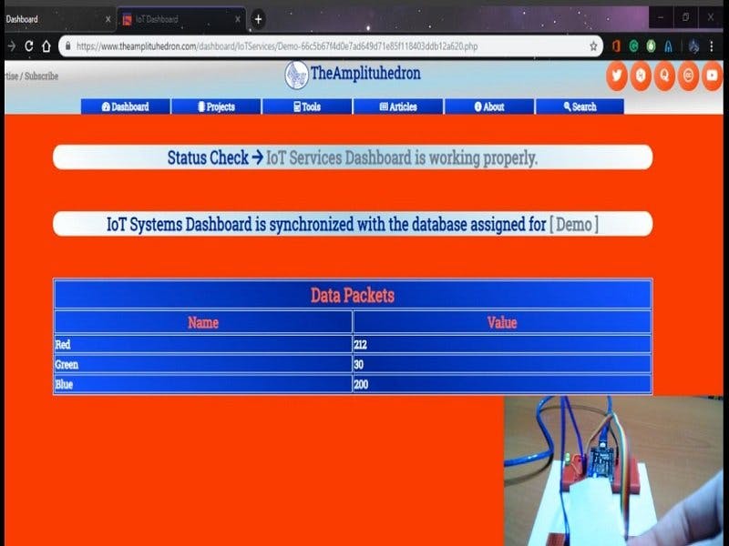
After the last step, astonishingly, you can monitor your data packets in every 5 seconds on your encrypted connection page, coming from your database table hosted on TheAmplituhedron server in order :)
By downloading TheAmplituhedron Mobile App in Android, you can view all the data packets provided by TheAmplituhedron IoT Services in collaboration with mobile features.
Also, you can use your default web browser to get data packets on mobile, especially on iOS.
Free TheAmplituhedron IoT Services | Send Colors in RGB Format | Hedron Authorization
Free TheAmplituhedron IoT Services | Send Colors in RGB Format | View Colors on your IoT Dashboard
Free TheAmplituhedron IoT Services | In Collaboration with TheAmplituhedron Mobile App


_3u05Tpwasz.png?auto=compress%2Cformat&w=40&h=40&fit=fillmax&bg=fff&dpr=2)

Comments