

Wooden tower block style games like Jenga have existed for ages... and 25+ years later I still remember the horrible ads, ugg. Catchy commercials aside, I generally like playing easy to learn, but highly competitive games like this with friends, and this one is as easy as it gets.
This project is an attempt to take the classic tower block game, and using a bunch of parts I already had laying around, see if I could add an audio element to it by embedding a small ARM MCU, an accelerometer, and a speaker/audio-amp inside a single block.
The goal is to detect any sort of motion, and play a customisable audio sample on the speaker when motion is detected, and (hopefully) add a bit more of a competitive edge when playing this with someone else. It's a WIP, and would benefit from a custom PCB daughterboard for the main MCU, but I was able to fit stuff I already had laying around (almost) into a block with a bit of butchery and dodgy soldering.
MCU SelectionI love working with small, super-low-cost ARM MCUs and it's amazing how much processing power you can get for not much more than $1 today, and it's always a fun challenge to see what you can do with these tiny, inexpensive but amazing devices.
I've been playing with the LPC845 lately since I try to keep up to date with that device family, and these entry-level chips have something that isn't common in this class of devices: not just one but two DACs, and a decent chunk of SRAM (16KB when 8KB is more common in this price range). That makes them a fun and ideal choice for audio projects like this! It also has a DMA engine to make it easy to send audio samples out to the DAC without tight timing constraints in the C code.
Technical OverviewAudio output is generated using a single DAC on the LPC845 (it has two for stereo output, but I only had room for one speaker!), with DMA transfers from the audio sample buffer to the DAC's output pin, into a small class-D audio amp, and out to a small 1W speaker that (mostly!) fits inside the wooden block.
The FXOS8700 3-axis accelerometer and magnetometer were used, but drivers are also present for the very similar MMA8652.
The following are the key parts used in the system
- LPC845-BRK(ridiculously cheap ARM Cortex M0+ dev board with on-board debugger!)
- Adafruit Precision NXP 9-DOF Breakout Board - FXOS8700 + FXAS21002
- Adafruit Mono 2.5W Class D Audio Amplifier - PAM8302
- Mini Oval Speaker - 8 Ohm 1 Watt
Software development was done using the free MCUXpresso IDE from NXP (on OS X in my case, but it also runs on Linux and Windows!). The LPC845-BRK board I was using has an on-board SWD debugger, so I just have to plug in a USB cable and I can flash, debug and get printf console output, etc.
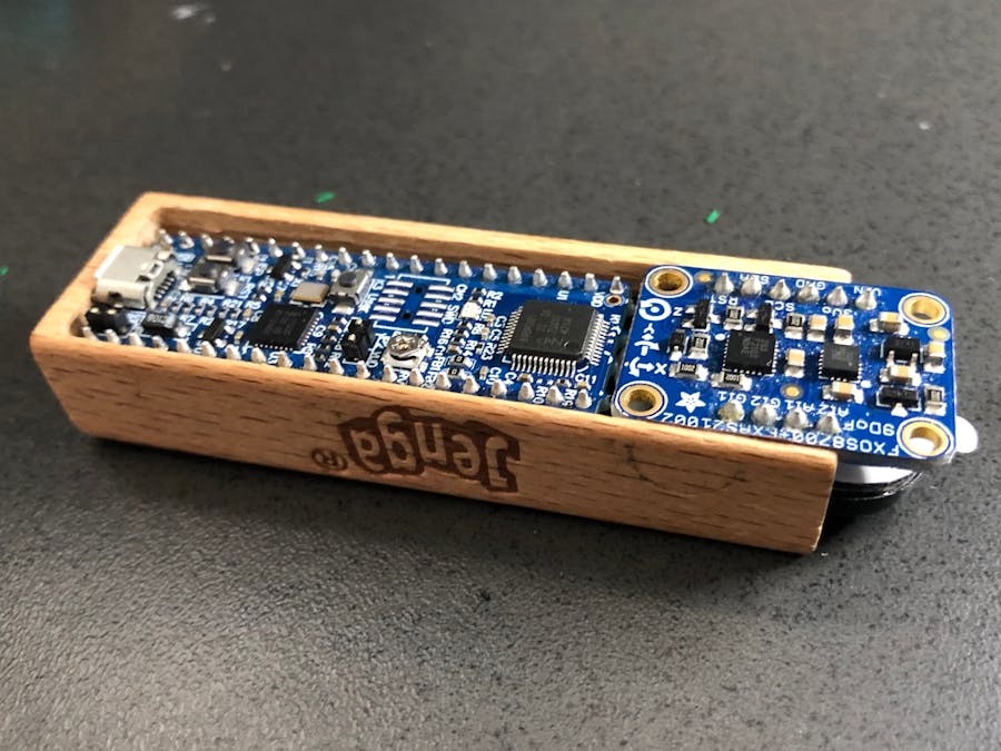
Initial PrototypeWhile a custom designed PCB would have made life easier, for the first prototype and proof of concept of this project I used off-the-shelf parts I already had laying around, although I did have to trim a millimeter or two off some of the boards to make them fit inside the wooden blocks.
I hollowed out a wooden block using a small CNC mill I have, driven by a Raspberry Pi and grblshield plus an Arduino Uno. You can see one attempt a milling below, based on a quick model put together in Autodesk Fusion 360:
PinoutThe various components of this project are connected as follows:
NOTE: The Adafruit breakout with the FXOS8700 is populated with pullup resistors on the SCL and SDA lines, so they don't need to be added to the project. If you are using a breakout WITHOUT these pullups, they will need to be added for the I2C bus to function correctly.
Using off the shelf components you already have is great since it's quick, convenient and (once you've already purchased them),... free. The down side is, you might end up with a tight fit if you're a bit space constrained like I was here. :P
I had to (carefully!) grind 1-2mm off the edge of some of the breakout boards with a small hobby drill, and then there was a mess of jumper wires to solder one, and some header pins to snip off or reduce the height of to make it all fit, but I mostly managed to make it work:
After (a bit too much) poking and prodding and carefully trying to tuck the wires underneath, I ended up with this, which you can still stack stuff onto, even though the first-round parts did end up sticking out the edge:
Clearly, no awards were won on workmanship here! :P
Software DesignThis project is fairly basic (thanks to the peripheral blocks on the LPC845!). It continually reads the input from the 3-axis accelerometer, and converts the raw accelerometer data into roll and pitch 'angles'. By tracking the current and previous angular positions, we detect when a change or more than 1° occurs.
The exact crossover threshold is adjustable, and is defined using the following macro:
/* Accelerometer delta (degrees to register as a valid motion event) */#define ACCEL_DELTA_DEGREES (1.0)
The DAC is configured to run at 8kHz (typical frequency for telephones, etc.), using DAC0 and DMA channel 22. You can adjust the frequency, but 8kHz is plenty, and keeps the audio sample buffer small as well.
The audio alert consists of a pre-defined array of 10-bit unsigned values (for the 10-bit DAC), which are fed to the DAC via DMA transfers whenever a motion 'event' is detected.
Every motion event that is detected (angular change >= ACCEL_DELTA_DEGREES) will queue one 'tick' for the audio output, and these 'ticks' will results in a sequence of blips, where the audio buffer is sent out one to the DAC. If a large amount of motion is detected, the audio alert will this become longer and more pronounced.
The color of the onboard LEDs will also change whenever a motion event is detected, to add a visual element for the hearing impaired, etc.
DemonstrationThe video below shows the relative sensitivity to motion of the part, and any sort of motion easily triggers a beep and the LEDs:
NOTE: The audio in the video above is relatively muted, but the sound is louder (and adjustable!) in real life. The audio was initially kept low to avoid blowing out the 1W speaker during initial testing.
The overall dimensions are slightly awkward, and I'll need to glue this down with a glue gun for stability, but as a first proof of concept and WIP, I'm happy with it and I'll continue to post updates on this as I design a custom daughter board for the LPC845-BRK.
Design FilesThe.step file for the wooden block used in this project can be seen below, but this is all of about 3 minutes work in Fusion 360 so it's provided more as a visual queue than anything else. The.step file is available in the Github repo if you want to 3D print it though! lpc845_wooden_block.step
Future DevelopmentsIt should be easy to update this code to play a different audio sample, detect free fall when the tower collapses, etc., depending on your own design goals. The aim of the project today was primarily to put all the pieces together for DMA-based audio, plus motion detection, as better mechanical options are pursued to the enclosure, and potentially a PCB daughter-board can be designed to be soldered to the LPC845-BRK to save space and add mechanical strength.
I'll post updates here as I continue to work on this and refine it into something more robust and capable of surviving more than one death plunge. :)


Comments